IFM DTE603 Manual de usuario

Installation instructions
RFID compact unit
DTE601
DTE602
DTE603
DTE604
80282046 / 00 02 / 2019
UK

2
Contents
1 Preliminary note���������������������������������������������������������������������������������������������������4
1�1 Symbols used ������������������������������������������������������������������������������������������������4
1�2 Warnings used�����������������������������������������������������������������������������������������������4
1�3 Copyright and trademarks �����������������������������������������������������������������������������4
2 Safety instructions �����������������������������������������������������������������������������������������������4
3 Functions and features ����������������������������������������������������������������������������������������5
3�1 Configuration via Ethernet interface ��������������������������������������������������������������6
4 Items supplied������������������������������������������������������������������������������������������������������6
5 Function���������������������������������������������������������������������������������������������������������������6
5�1 Operating principle ����������������������������������������������������������������������������������������6
5�2 Overview DTE601������������������������������������������������������������������������������������������7
5�3 Overview DTE602������������������������������������������������������������������������������������������7
5�4 Overview DTE603������������������������������������������������������������������������������������������7
5�5 Overview DTE604������������������������������������������������������������������������������������������8
6 Installation������������������������������������������������������������������������������������������������������������8
6�1 General installation instructions���������������������������������������������������������������������8
6�2 Notes on ID tag mounting������������������������������������������������������������������������������8
6�3 Avoiding interference �������������������������������������������������������������������������������������8
6�4 Mechanical design�����������������������������������������������������������������������������������������9
6�5 Installation options�����������������������������������������������������������������������������������������9
6�5�1 Installation with angle bracket E80335 �������������������������������������������������9
6�5�2 Installation with mounting device E80336 ������������������������������������������10
6�5�3 Installation with fixing bars E80337 ����������������������������������������������������10
6�6 Mounting distances�������������������������������������������������������������������������������������� 11
6�7 Positioning of the ID tags����������������������������������������������������������������������������� 11
7 Electrical connection������������������������������������������������������������������������������������������12
7�1 Voltage supply PWR������������������������������������������������������������������������������������12
7�2 Ethernet �������������������������������������������������������������������������������������������������������13
7�2�1 Factory setting of the Ethernet parameters ����������������������������������������13
7�3 Functional earth connection ������������������������������������������������������������������������14
7�3�1 Mounting plate ������������������������������������������������������������������������������������14
8 Operating and display elements ������������������������������������������������������������������������15
8�1 Reset to factory settings ������������������������������������������������������������������������������15

3
UK
8�2 LED indicators ���������������������������������������������������������������������������������������������16
8�2�1 Power LEDs and signal bar ����������������������������������������������������������������16
8�2�2 LED LINK/ACT ETH 1 / ETH 2 �����������������������������������������������������������16
8�2�3 Special device LED indicators ������������������������������������������������������������17
8�3 LED indicators DTE601 �������������������������������������������������������������������������������18
8�3�1 LED SF �����������������������������������������������������������������������������������������������18
8�3�2 LED BF �����������������������������������������������������������������������������������������������18
8�4 LED indicators DTE602 �������������������������������������������������������������������������������19
8�4�1 LED Mod (module status)�������������������������������������������������������������������19
8�4�2 LED Net (network status) �������������������������������������������������������������������20
8�5 LED indicators DTE603 �������������������������������������������������������������������������������21
8�5�1 RUN LED �������������������������������������������������������������������������������������������21
8�5�2 LED ERR ��������������������������������������������������������������������������������������������21
8�6 LED indicators DTE604 �������������������������������������������������������������������������������22
8�6�1 LED SF �����������������������������������������������������������������������������������������������22
8�6�2 LED BF �����������������������������������������������������������������������������������������������22
9 Technical data����������������������������������������������������������������������������������������������������23
9�1 Data sheet ���������������������������������������������������������������������������������������������������23
9�2 Device manual���������������������������������������������������������������������������������������������23
10 Maintenance, repair and disposal��������������������������������������������������������������������23
11 Approvals/standards ����������������������������������������������������������������������������������������23
11�1 Radio approvals�����������������������������������������������������������������������������������������23
11�1�1 Overview�������������������������������������������������������������������������������������������23
11�1�2 Europe ����������������������������������������������������������������������������������������������23
11�2 EU declaration of conformity����������������������������������������������������������������������23
12 Scale drawing ��������������������������������������������������������������������������������������������������24

4
1 Preliminary note
Technical data, approvals, accessories and further information →
www�ifm�com�
1.1 Symbols used
►Instruction
> Reaction, result
[…] Designation of keys, buttons or indications
→Cross-reference
Important note
Non-compliance may result in malfunction or interference�
Information
Supplementary note
1.2 Warnings used
ATTENTION!
Kind and source of the hazard
> Possible consequences�
►Actions to refrain from�
►Measures to take�
1.3 Copyright and trademarks
© All rights reserved by ifm electronic gmbh� No part of these instructions may be
reproduced and used without the consent of ifm electronic gmbh�
All product names, pictures, companies or other brands used on our pages are the
property of the respective rights owners�
2 Safety instructions
• The device described is a subcomponent for integration into a system�
- The manufacturer is responsible for the safety of the system�
- The system manufacturer undertakes to perform a risk assessment and to
create a documentation in accordance with legal and normative requirements
to be provided to the operator and user of the system� This documentation
must contain all necessary information and safety instructions for the operator,

5
UK
the user and, if applicable, for any service personnel authorised by the
manufacturer of the system�
• Read this document before setting up the product and keep it during the entire
service life�
• The product must be suitable for the corresponding applications and
environmental conditions without any restrictions�
• Only use the product for its intended purpose (→ Functions and features).
• If the operating instructions or the technical data are not adhered to, personal
injury and/or damage to property may occur�
• The manufacturer assumes no liability or warranty for any consequences
caused by tampering with the product or incorrect use by the operator�
• Installation, electrical connection, set-up, operation and maintenance of the
product must be carried out by qualified personnel authorised by the machine
operator�
• Protect the device and the cables against damage�
• Use the device outside petrol stations, fuel depots, chemical plants or blasting
operations�
• Do not transport and store any flammable gases, liquids or explosive
substances near the device�
• Operation of the device can affect the function of electronic devices that are not
correctly shielded�
- Disconnect the device in the vicinity of medical equipment�
- Contact the manufacturer of the corresponding device in case of any
interference�
• Because of the requirements for electromagnetic interference emissions, the
device is intended for use in industrial environments� The device is not suitable
for use in domestic areas�
• Device safety: Use the device indoors only�
3 Functions and features
The DTE60x device is composed of an evaluation unit and an integrated RFID
compact unit with the following functions:
• read and write ID tags which conform to the system without contact,

6
• DTE601: communication with the control level via PROFINET IO,
• DTE602: communication with the control level via EtherNet/IP,
• DTE603: communication with the control level via EtherCAT,
• DTE604: communication with the control level via EtherNet TCP/IP,
• can be configured via a web server�
Example applications:
• material flow control in production lines
• warehouse management by the automatic detection of stored products
• tank management, order picking or product tracking
The device may only be used under the operating conditions specified in
the data sheet�
3.1 Configuration via Ethernet interface
• 10 Mbps and 100 Mbps
• TCP/IP - Transport Control Protocol / Internet Protocol
• IT functionality: HTTP server
• M12, twisted pair
4 Items supplied
• DTE60x RFID compact unit
• Installation instructions
The device is supplied without installation and connection accessories�
In the event of incomplete or damaged items supplied, please contact ifm
electronic�
5 Function
5.1 Operating principle
The ID tags are operated passively, i�e� without battery� The energy required for
operation is supplied by the RFID compact unit�
The physical principle of the energy transfer is based on inductive coupling� The
integrated antenna coil in the RFID compact unit generates a magnetic field

7
UK
which partly penetrates the antenna coil of the ID tag� A voltage is generated by
induction that supplies the data carrier with energy�
5.2 Overview DTE601
Art� no�:
Function:
Type designation:
Operating frequency:
Type:
Max� transmitter power:
DTE601
RFID compact unit
DTRHF HLRWPNUS03
13�56 Mhz
rectangular
2 watts
Fig� 1: Overview DTE601
5.3 Overview DTE602
Art� no�:
Function:
Type designation:
Operating frequency:
Type:
Max� transmitter power:
DTE602
RFID compact unit
DTRHF HLRWEIUS03
13�56 Mhz
rectangular
2 watts
Fig� 2: Overview DTE602
5.4 Overview DTE603
Art� no�:
Function:
Type designation:
Operating frequency:
Type:
Max� transmitter power:
DTE603
RFID compact unit
DTRHF HLRWECUS03
13�56 Mhz
rectangular
2 watts
Fig� 3: Overview DTE603

8
5.5 Overview DTE604
Art� no�:
Function:
Type designation:
Operating frequency:
Type:
Max� transmitter power:
DTE604
RFID compact unit
DTRHF HLRWENUS03
13�56 Mhz
rectangular
2 watts
Fig� 4: Overview DTE604
6 Installation
6.1 General installation instructions
When mounting several RFID compact units adhere to the minimum
distances between the systems�
Installing a RFID compact unit in or on metal reduces the read and write
distance�
The immediate vicinity of powerful HF emission sources such as welding
transformers or converters can affect operation of the RFID compact units�
Available accessories: www�ifm�com
6.2 Notes on ID tag mounting
Installation of the ID tags in and on metal reduces the read and write
distances�
For positioning the ID tags the RFID compact units are marked with
an antenna symbol on the active face� It designates the middle of the
integrated antenna coil and has to correspond with the middle of the ID tag�
The orientation of the RFID compact unit axis must correspond with the
axis of the ID tag coil�
6.3 Avoiding interference
The device generates a modulated electrical field with a frequency of 13�56 MHz�
To avoid interference of the data communication no other devices generating
interference emission in this frequency band must be operated in its vicinity� Such
devices are for example frequency converters and switched-mode power supplies�

9
UK
6.4 Mechanical design
1
2
1: sensing face
2: connection (can be rotated by 270°)
Fig� 5: Mechanical design
6.5 Installation options
For installation, the following optional accessories are available�
The device can be mounted without the accessories� For installation,
please use the threaded sleeves on the back of the device� The necessary
screws are not supplied with the device�
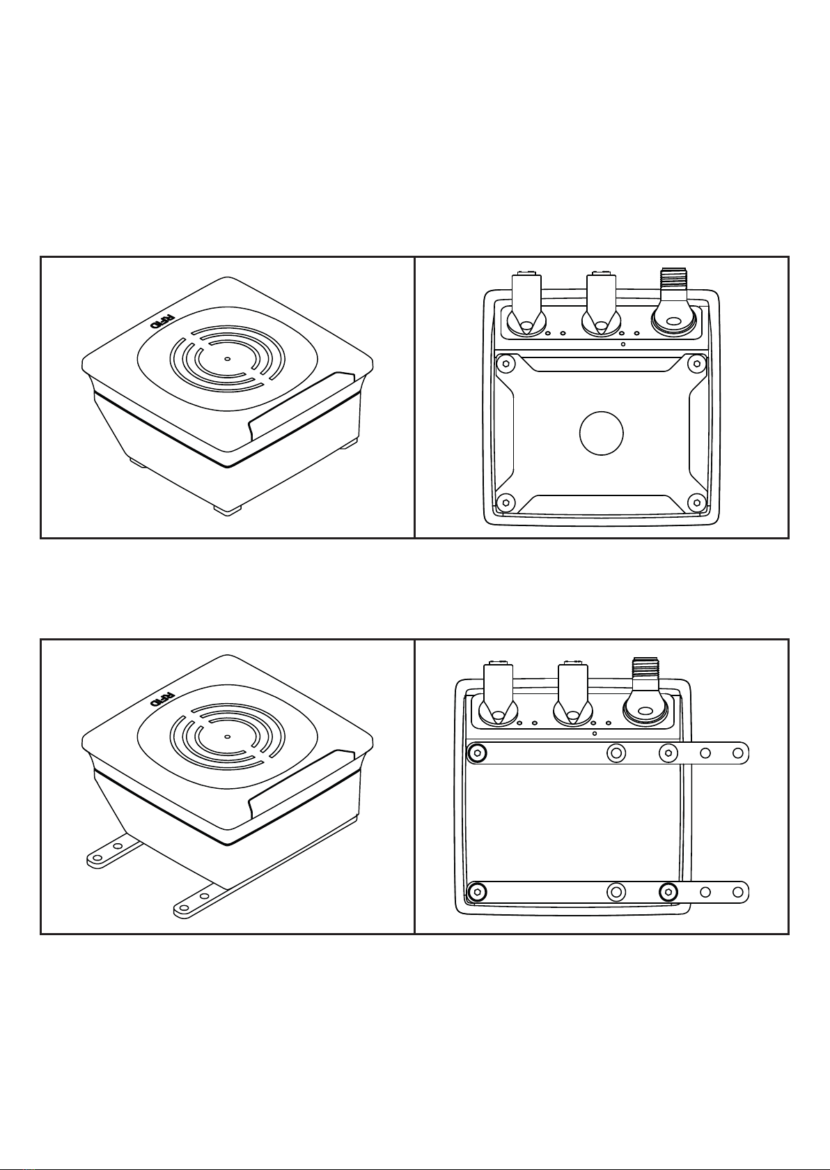
6.5.1 Installation with angle bracket E80335
Fig� 6: Installation with angle bracket E80335
10
6.5.2 Installation with mounting device E80336
The mounting device is used to fix the device to a clamp� The following clamps
can be used:
• E21110 with a rod diameter of 12 mm
• E20795 with a rod diameter of 14 mm
• E21109 with a rod diameter of 14 mm
Fig� 7: Installation with mounting device E80336
6.5.3 Installation with fixing bars E80337
Fig� 8: Installation with fixing bars E80337
►Fix the device with fixing screws to the designated location�
Este manual sirve para los siguientes modelos
3
Tabla de contenidos
Otros manuales de Sistema RFID de IFM

IFM
IFM DTM436 Manual de usuario

IFM
IFM DTE801 Manual de usuario

IFM
IFM ANT515 Manual de usuario

IFM
IFM DTI515 Manual de usuario

IFM
IFM DTM424 Manual de usuario

IFM
IFM DTC600 Manual de usuario

IFM
IFM ANT513 Manual de usuario

IFM
IFM ANT434 Manual de usuario

IFM
IFM DTC510 Manual de usuario

IFM
IFM ANT600 Manual de usuario

IFM
IFM DTM426 Manual de usuario

IFM
IFM DTE601 Manual de usuario

IFM
IFM DTE801 Manual de usuario

IFM
IFM DTI434 Manual de usuario

IFM
IFM DTI600 Manual de usuario

IFM
IFM DTE102 Guía de aplicación

IFM
IFM DTI420 Manual de usuario

IFM
IFM DTC600 Manual de usuario

IFM
IFM ANT420 Manual de usuario

IFM
IFM DTI513 Manual de usuario


