HBM TB1A Manual de usuario

A01627.0 en/de/fr
Reference
torque measuringdisc
Referenz
Drehmomentmessscheibe
Couplemètre
disque de référence
TB1A
Mounting instructions
Montageanleitung
Notice de montage

English Page 3 − 25. . . . . . . . . . . . . . . . . . . . . . . . . . . . . . . . . . . . . . . . . . . . . . .
Deutsch Seite 27 − 49. . . . . . . . . . . . . . . . . . . . . . . . . . . . . . . . . . . . . . . . . . . . . .
Français Page 51 − 73. . . . . . . . . . . . . . . . . . . . . . . . . . . . . . . . . . . . . . . . . . . . . .

3
TB1A
HBMA01627.0en/de/fr
Contents Page
Safety instructions 4. . . . . . . . . . . . . . . . . . . . . . . . . . . . . . . . . . . . . . . . . . . . . . .
1 Scope of supply 8. . . . . . . . . . . . . . . . . . . . . . . . . . . . . . . . . . . . . . . . . . . . . .
2Application 8. . . . . . . . . . . . . . . . . . . . . . . . . . . . . . . . . . . . . . . . . . . . . . . . . .
3Structure and mode of operation 9. . . . . . . . . . . . . . . . . . . . . . . . . . . . . .
3.1 Mechanical structure 9. . . . . . . . . . . . . . . . . . . . . . . . . . . . . . . . . . . . .
4 Mounting 9. . . . . . . . . . . . . . . . . . . . . . . . . . . . . . . . . . . . . . . . . . . . . . . . . . . .
4.1 General installation notes 9. . . . . . . . . . . . . . . . . . . . . . . . . . . . . . . . .
4.2 Mounting position 12. . . . . . . . . . . . . . . . . . . . . . . . . . . . . . . . . . . . . . . .
4.3 Conditions on site 12. . . . . . . . . . . . . . . . . . . . . . . . . . . . . . . . . . . . . . .
4.4 Mechanical installation 12. . . . . . . . . . . . . . . . . . . . . . . . . . . . . . . . . . .
4.5 Loading capacity 18. . . . . . . . . . . . . . . . . . . . . . . . . . . . . . . . . . . . . . . .
5 Electrical connection 19. . . . . . . . . . . . . . . . . . . . . . . . . . . . . . . . . . . . . . . . .
5.1 Notes for cabling 20. . . . . . . . . . . . . . . . . . . . . . . . . . . . . . . . . . . . . . . .
5.2 Fourwire technique 21. . . . . . . . . . . . . . . . . . . . . . . . . . . . . . . . . . . . . .
6 Maintenance 21. . . . . . . . . . . . . . . . . . . . . . . . . . . . . . . . . . . . . . . . . . . . . . . . .
7Accessories 21. . . . . . . . . . . . . . . . . . . . . . . . . . . . . . . . . . . . . . . . . . . . . . . . .
8 Specifications 22. . . . . . . . . . . . . . . . . . . . . . . . . . . . . . . . . . . . . . . . . . . . . . .
9Dimensions 25. . . . . . . . . . . . . . . . . . . . . . . . . . . . . . . . . . . . . . . . . . . . . . . . . .

4TB1A
HBM A01627.0en/de/fr
Safety instructions
Use in accordance with the regulations
Reference torque measuringdiscs TB1A are used exclusively for torque
measurement tasks and control and adjustment tasks directly connected
thereto. Use for any additional purpose shall be deemed to be not in
accordance with the regulations.
In the interests of safety, the transducer should only be operated as described
in the Mounting Instructions. It is also essential to observe the appropriate
legal and safety regulations for the application concerned during use. The
same applies to the use of accessories.
The transducer is not a safety element within the meaning of its use as in
tended. Proper and safe operation of this transducer requires proper
transportation, correct storage, assembly and mounting and careful operation.
General dangers of failing to follow the safety instructions
The transducer corresponds to the state of the art and is failsafe. The
transducer can give rise to remaining dangers if it is inappropriately installed
and operated by untrained personnel.
Everyone involved with the installation, commissioning, maintenance or repair
of the transducer must have read and understood the Operating Manual and
in particular the technical safety instructions.
Remaining dangers
The scope of supply and performance of the transducer covers only a small
area of torque measurement technique. In addition, equipment planners,
installers and operators should plan, implement and respond to the safety
engineering considerations of torque measurement technique in such a way
as to minimize remaining dangers. Prevailing regulations must be complied
with at all times. Reference must be made to remaining dangers connected
with torque measurement technology.

5
TB1A
HBMA01627.0en/de/fr
In this Mounting Instruction remaining dangers are pointed out using the
following symbols:
Symbol: DANGER
Meaning: Highest level of danger
Warns of a directly dangerous situation in which failure to comply with safety
requirements will lead to death or serious physical injury.
Symbol: WARNING
Meaning: Possibly dangerous situation
Warns of a potentially dangerous situation in which failure to comply with
safety requirements can result in death or serious physical injury.
Symbol: CAUTION
Meaning: Potentially dangerous situation
Warns of a potentially dangerous situation in which failure to comply with
safety requirements could result in damage to property or some form of
physical injury.

6TB1A
HBM A01627.0en/de/fr
Symbols pointing out notes on use and waste disposal as well as useful
information:
Symbol: NOTE
Means that important information about the product or its handling is being
given.
Symbol:
Meaning: CE mark
The CE mark enables the manufacturer to guarantee that the product com
plies with the requirements of the relevant ECdirectives (the declaration of
conformity is available at http://www.hbm.com/HBMdoc).
Symbol:
Meaning: Statutory marking requirements forwaste disposal
National and local regulations regarding the protection of the environment and
recycling of raw materials require old equipment to be separated from regular
domestic waste for disposal.
For more detailed information on disposal, please contact the local authorities
or the dealer from whom you purchased the product.

7
TB1A
HBMA01627.0en/de/fr
Conversions and modifications
The transducer must not be modified from the design or safety engineering
point of view except with our express agreement. Any modification shall ex
clude all liability on our part for any damage resulting therefrom.
Qualified personnel
Qualified personnel means persons entrusted with the installation, fitting,
commissioning and operation of the product who possess the appropriate
qualifications for their function.
The transducer must only to be installed and used by qualified personnel,
strictly in accordance with the specifications and with safety requirements and
regulations. It is also essential to observe the appropriate legal and safety re
gulations for the application concerned during use. The same applies to the
use of accessories.
Prevention of accidents
According to prevailing accident prevention regulations, it is essential that
after mounting the transducers the user fits a cover or enclosure as follows:
•The cover or enclosure must not be able rotate.
•The cover or enclosure shall protect against crushing or cutting and provide
protection against parts that might come loose.
•The covers and enclosures shall be installed at a safe distance from
moving parts or shall prevent anyone putting their hand inside.
•The covers and enclosures shall even be fitted if the moving parts are
installed in areas to which persons do not usually have access.
The above regulations may only be diverged from, if machine parts are
already sufficiently protected owing to the design of the machine or because
other precautions have been taken.

8TB1A
HBM A01627.0en/de/fr
1 Scope of supply
The scope of supply includes the following:
1Reference torque measuringdisc
1 Mounting Instructions
1 Test record
2Application
Transducers measure static and dynamic torques in nonturning mode. The
nominal torques fall within the range 100 N⋅m to 10kN⋅m.
Transfertorque transducer
The main applications are torque transfer, for example, when calibrating
reference transducers in test and calibration machines and comparisons of
the reference normals of various calibration laboratories.
In the case of transfer transducers, a high degree of comparability is import
ant, as when relaying torque, this provides a gage for various observers, test
conditions, laboratories and the installation and time situation. So for relay, the
same installation conditions should be created as for calibration in the refe
rence normal, or relevant adapters (for recommendations, see Page 17f)
should be included in the calibration.
Reference torque transducer
Reference torque transducers are mounted in a calibration device and then
the entire calibration machine is qualified or certified by means of transfer
torque transducers, for example. The precise sensitivity of the transducer is
thus less important.
General torque measurements in nonturning mode
Because of the high mechanical loading capacity, the permissible vibration
bandwidth of 160% (10kN⋅m=120%) of nominal torque and the compact
design, the transducers are also eminently suitable for use in testing
machines for component testing (rotary alternating stress) or as reaction
torque transducers, for example in agitators with direct drive motor or gearbox
connection.

9
TB1A
HBMA01627.0en/de/fr
3Structure and mode of operation
3.1 Mechanical structure
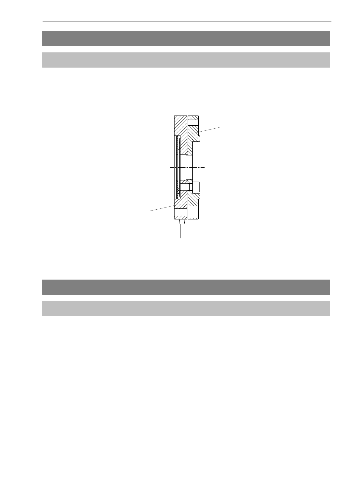
The reference torque measuringdisc comprises a measuring body applied
with strain gages and a mounting flange screw fitted to it.
Measuring body
Mounting flange
Measuring side
Fig.3.1: Mechanical structure
4 Mounting
4.1 General installation notes
When the torque measuringdisc is fitted in test benches, the test bench
components (frame, couplings, mounting flanges, screw fittings, etc.), affect
the deflection performance in the shaft run and thus the measuring
characteristics (zero point, sensitivity, reproducibility). The causes for this can
include:
•Additional parasitic loadings such as radial forces, axial forces or bending
moments
•Asymmetrical torque introduction in the transducers

10 TB1A
HBM A01627.0en/de/fr
•Different stiffness conditions in the shaft run to those of transducer
calibration
These test bench reactions on the reference transducer are calibrated in by
adaptable leverground systems, for example.
Torque transducer
to be calibrated
Blocking device
TB1A
Leverforce device
for static torque
Calibration test device with
reference transducer
Fig.4.1: Typical installation in a calibration test device
Parasitic loadings
Parasitic loadings are caused by deformations in the shaft run. They result in
an additive effect on the zero signal of the torque measuringdisc (see
Specifications). If they occur during a torque loading, they cause an apparent
change in sensitivity.
Countermeasures:
1. Optimum alignment of the shaft run (note alignment data in the
Specifications!).
As long as you do not exceed the permissible limits for bending moments,
transverse force and longitudinal force, no special couplings or other
measures are required to install the reference torque measuringdisc
(effect on the measurement result approx. 1% of nominal torque).
Otros manuales para TB1A
1
Tabla de contenidos
Idiomas:
Otros manuales de Transductor de HBM

HBM
HBM P6A Manual de usuario

HBM
HBM Z8 Manual de usuario

HBM
HBM AED9101C-Z2/22 Actualización de firmware

HBM
HBM Z30 Manual de usuario

HBM
HBM TB2 Manual de usuario

HBM
HBM U3 Manual de usuario

HBM
HBM Paceline CFT Manual de usuario

HBM
HBM C18 Manual de usuario

HBM
HBM TB1A Manual de usuario

HBM
HBM C9B Manual de usuario
Manuales populares de Transductor de otras marcas

Camille Bauer
Camille Bauer SINEAX F534 Manual de usuario

Trane
Trane KIT 16724 Instrucciones de montaje

Lumel
Lumel P18 Manual de usuario

B&C Speakers
B&C Speakers DE75PTN Manual de usuario

MAMAC SYSTEMS
MAMAC SYSTEMS PR-243 Manual

Mianyang Weibo Electronic
Mianyang Weibo Electronic WB Series Manual de usuario