Wall surface
45 ± 10mm
Refer to Note 2
Recommended
height
Battery box
1.
2.
3.
4.
5.
6.
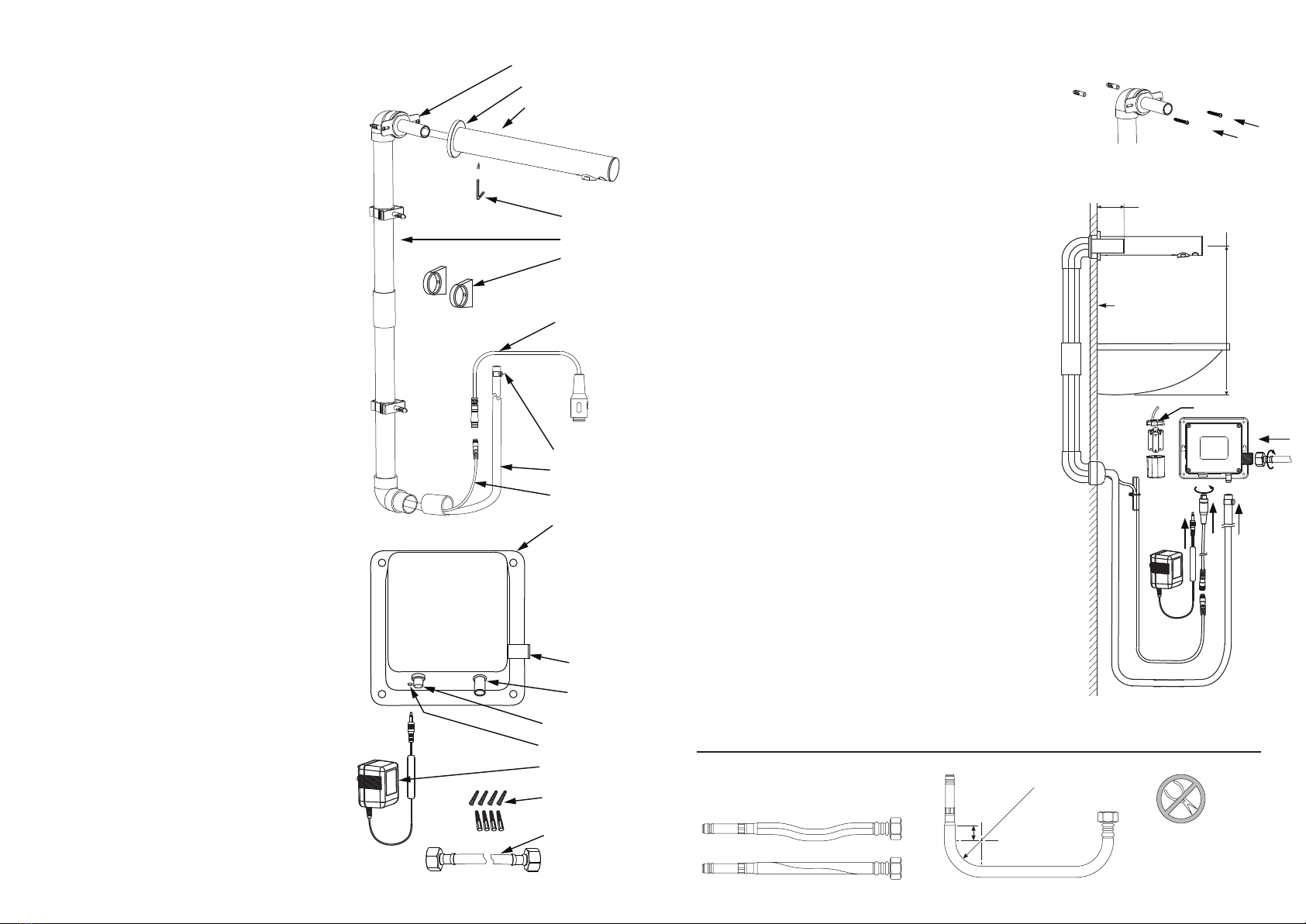
Assemble the PVC duct and arrange within the
wall cavity.
Position the mounting bracket at the desired height
above the proposed bench top. REFER TO WARNING
FOR RECOMMENDED SPOUT POSITION.
Set the mounting bracket against a vertical or
horizontal beam. The brass support tube must protrude
a minimum of 35mm from the finished wall surface.
Check the bracket is level and install with screws. The
duct clamps can be used to secure the lower PVC duct.
The finished wall surface requires a 30 ± 4mm clearance
hole for the brass tube, and a 33mm hole for the
under-bench duct. Seal flush with silicone.
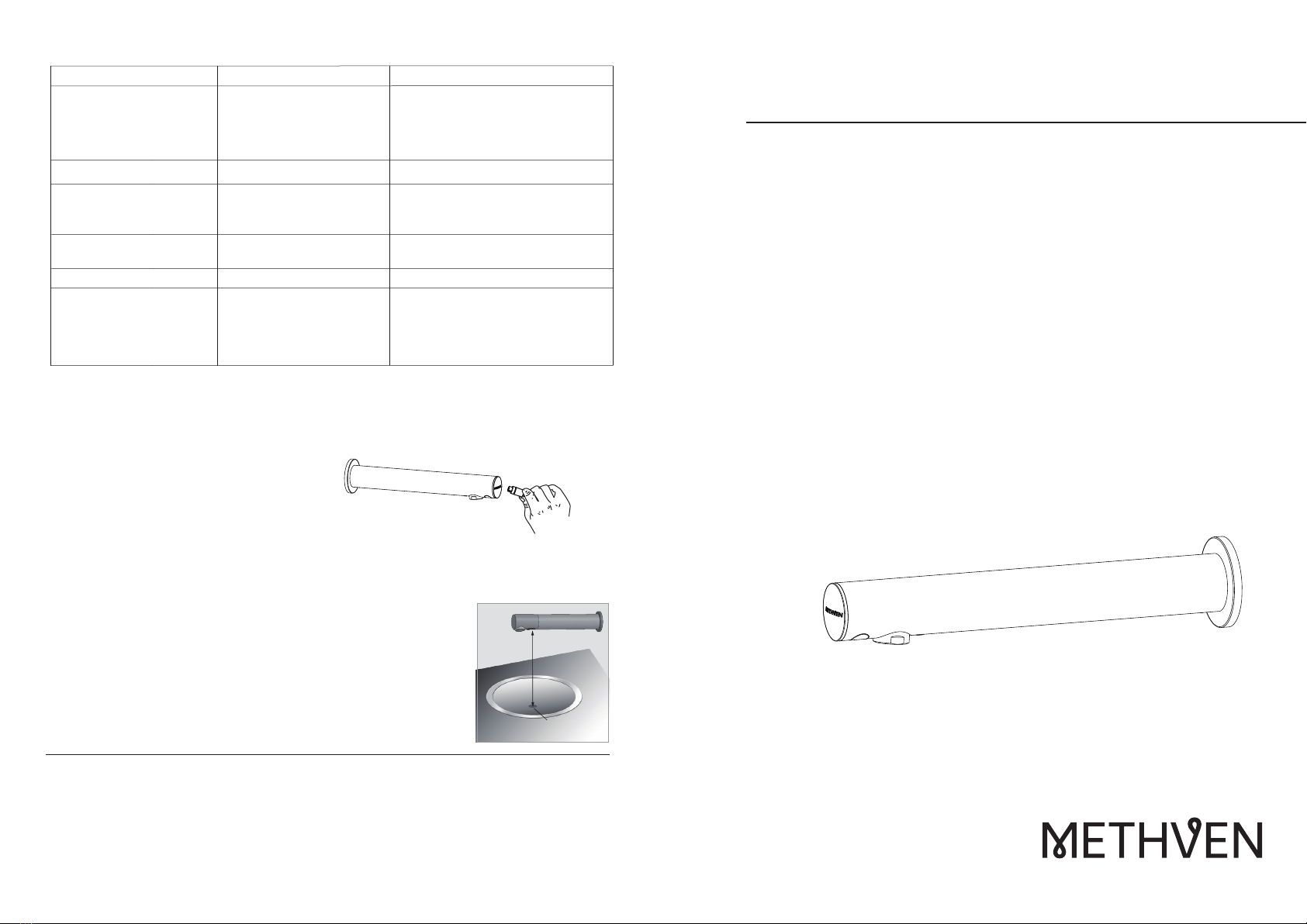
Slide the faceplate over the exposed mounting bracket
brass tube.
Disconnect the sensor adapter cable from the sensor
harness. Using a “fish-tape” or similar, draw the sensor
harness and delivery hose through the mounting bracket
and PVC duct. Fasten the spout securely with the hex key.
Open the control box. Remove, and open, the battery box.
Insert 4 x 1.5V AA batteries into the battery box, confirm
the correct polarity, re-install the battery box and close
the control box.
Position the control box, in a dry location. Ensure that all
connections have easy access and install the control box
securely.
Clamp the delivery hose to the control box outlet, and the
water supply to the control box inlet and check for leaks.
Connect the sensor cable to the control box,
Plug the transformer cable into the control box and the
transformer into the 220V AC supply
Remove the cover tape from the spout sensor window.
Installation:
7.
8.
9.
10.
11.
12.
13.
Control Box
with Battery box
Water outlet
Sensor connection
Power supply port
Water Inlet
Mounting screws
Water Inlet hose
AC transformer
Faceplate
Spout
Hex key
PVC duct
Sensor adapter
Hose clamp
Delivery hose
Sensor harness
Mounting bracket
Duct clamps
•
•
•
•
•
•
•
•
•
IMPORTANT: Please read all of the
instructions before installation.
General:
Methven recommends this product is installed
by a licensed plumber in compliance with all
relevant regional regulations.
Do not hydrostatic test the installation with
this mixer installed. Damage to the
mechanism may occur.
All pipe work must be thoroughly flushed prior
to the installation of the mixer.
In-line filters must be fitted on both hot and
cold supplies to prevent foreign particles
damaging the mechanism.
Do not install in direct sunlight.
After installation all connections must be
checked for leaks.
All outlets used primarily for personal hygiene
shall deliver water at a safe temperature as per
regional regulations.
This mixer is not recommended for use in
uncontrolled heating systems such as
wet-backs or solar heating units unless a
suitable tempering valve is fitted.
If limited water flow is experienced, locate
aerator and filter washers and clean away
foreign material as required.
It is the responsibility of the installer to ensure
a waterproof seal is achieved between the
product and mounting surface. If in doubt
about the quality of the seal, remove the
product and reinstall using silicone to ensure a
seal is achieved.
Correct
Incorrect
Do not stretch or twist hose
DO NOT crush
Hose or swaged
Ends
R35mm Min
20mm
•