New lift FST-2s Manual de usuario

Replacing FST-2s with FST-2XTs
MANUAL
FST-2s
X37
X23
X17
X16
K37 K38 K39 K40
J131
J133
J135
J137
X111
X7/JTAG
J1/SERVICE
VORSICHT!
Explosionsgefahr bei
unsachgemäßem Austausch
der CR2430 Lithium-Batterie.
Entsorgung nur nach
Betriebsanleitung.
X2/GST-2s
K37: FK-SET
K38: Option1/FK-RESET
K39: Option2/GG-SET
K40: Option3/GG-RESET
J2
K23
K22
K21
K20
X19
X14
Notruf
X32
X21
X20
K7 K8 K9 K10 K11
FST-2s V2.Xc
K12 K1 K2 K3 K4 K0 K5 K6
Serien-
nummer
GEBER-B
GEBER-A
Zone
0
11
X2
K23
J131
J135
J136
X41X7
GESCHLOSSEN
>A<
01
Enter
Drive
Shift
F1 F2
AA
B
A
EVAC
AUX
FUNC Select
11
SKZU
SP
TKA
TKB
TKC
NHLT
FKNH
X5 X6 X3
BR
TEST R1/R2
1 0
S1000 S141 S140
S143/S207 S206 S205
S25
S998
IN
OUT
E
S
F
X2
HHT
1 2
X4
123 4 5678 9 10 11 12 13 14 15 16 17 18 19 20 21 22 23 24
X1
K37
K38 X30
1
K22
K21
K20
X16
K14
X17
X19
X14
X21
X20
K13
X18 X24 X25 X26
K7
K6
K5
K0
K4
K3
K2
K1
K12
K11
K10
K9
K8
J133
14:03 : 02
1 3 4 6 7 8 2 3 5 6 7
1 2 3 4 5 6 7 8 129 10 11 14 15 16 1713
1 2 3 4 5 6 7 8 129 10 11
1234 21 1 2 3 4 1 2 3 4 5 6 7 8 9
1
1 2 3 4
84
91213 11 10 7 6 5
X15
1 2 3 40
3 2 X13 14
2 3 4 5 6 2 3 4 2 3X23 X27 X28
2 3 41
65
D22 X32
FST-2XTs
>
SAFETY CCT CLOSED
>AX< >BX< '''@'''
0 0 13:06:56

ManualforreplacingFST-2swithFST-2XTs
Manufacturer NEWLIFTSteuerungsbauGmbH
LochhamerSchlag8
82166Graefelfing
Tel +49 89 – 898 66 – 0
Fax +49 89 – 898 66 – 300
Mail [email protected]
www.newlift.de
Service line Tel +49 89 – 898 66 – 110
Mail [email protected]
Date of issue 21.12.2015
Author AL/DSI
Release AL
Hardware version FST-2XTs:51-00-3.1-FST_2XTs_MAIN
FST-2s:V2.8
Software version V2.000-0111
Doc. No. hb_Austausch_FST-2saufFST-2XTs_2016-03_en
Copyright ©NEWLIFTSteuerungsbauGmbH,2016
Thismanualisprotectedbycopyright.Allrights,includingthoseofcopying,of
reproduction,oftranslationandofmodification,inwholeorinpart,arereservedby
thepublisher.
Nopartofthisdescriptionmaybereproducedinanyformorcopiedwithan
electronicreplicationsystemwithoutwrittenpermission.
Althoughgreatcarehasbeentakenintheproductionoftextsandfigures,we
cannotbeheldlegallyliableforpossiblemistakesandtheirconsequences.

ManualforreplacingFST-2swithFST-2XTs 3
Content
1 General 5
1.1 Abbreviations, characters and symbols used 5
1.2 Further information 5
1.3 How to contact us 5
1.4 General safety regulations 6
1.4.1 Applicablestandardsandguidelines 6
1.4.2 Electromagneticcompatibility(EMC) 6
1.4.3 Handlingelectronicassemblies 6
2 FST-2XTs compared to FST-2s 7
3 FST jumpers 9
4 Terminal strips 13
4.1 Overview of terminal strips relevant to replacement 13
4.2 Adaptation table 17
5 Replacing FST-2s with FST-2XTs 18
5.1 Data transfer 18
5.1.1 DatatransferviaLONbus 18
5.1.2 Datatransferviaserialinterface(alternative) 20
5.2 Removal 22
5.3 Installation 22
5.4 Function tests 23
5.5 Information on EN81-1/2:1998 + A3:2009 25
5.5.1 FunctionUCM-A3 25
5.6 Waste disposal 26
5.7 Appendix 26

4 ManualforreplacingFST-2swithFST-2XTs

General
Abbreviations,charactersandsymbolsused
ManualforreplacingFST-2swithFST-2XTs 5
1 General
This manual is intended to simplify the replacement of the FST-2s circuit board with the FST-2XTs circuit board.
► Read this manual carefully and observe the FST-2s/XTs Installation & Commissioning manual as well as the
included circuit diagrams and jumper settings for the circuit boards before beginning the replacement.
► After replacing, perform the tests listed under certicates “FST-2XTs 51 00 - notices” on pages 1 and 3.
► Update the documents of the lift system on-site as well as other documents that may be present at the “desi-
gnated entity”. A check of the parameters and functions transferred from the FST-2s circuit board or of the
NEW LIFT factory parameter set is the responsibility of the person who performs the replacement.
As assistance here, the test actuations as described in the FST-2XT or FST-2XTs Installation & Commissioning
manual under 6.7.4 are to be performed. The FST-2XTs circuit board is generally compatible with the FST-2s
circuit board. There are, however, additional functions resulting from further developments, relating to the EN81-
1/2:1998 + A3:2009 A3 in particular, that are to be observed.
1.1 Abbreviations, characters and symbols used
EAZ position indicators
Delivery condition
Settings that are supplied as standard are marked with an asterisk .
► Activity symbol:
Activities described after this symbol must be carried out in the given order.
Safety-relevant information
This symbol is located in front of safety-relevant information.
Information notice
This symbol is located in front of relevant information.
1.2 Further information
The following documents, among others, are available for the FST control system and its components:
› FST Installation & Commissioning
› FST manual
› ADM manual
› FPM manual
› SAM manual
› EAZ-256 manual
› EAZ-LCD and EAZ-VFD manual
› Fire recall manual
These and other current manuals can be found in the download area of our website under Service at http://
www.newlift.de/en/service/download
1.3 How to contact us
If, after referring to this manual, you still require assistance, our service line is there for you:
Tel +49 89 – 898 66 – 110
Mail [email protected]
Mon. - Thurs.: 8:00 a.m. – 12:00 p.m. and 1:00 p.m. – 5:00 p.m.
Fr: 8:00 a.m. – 3:00 p.m.

General
Generalsafetyregulations
6 ManualforreplacingFST-2swithFST-2XTs
1.4 General safety regulations
The FST-2XTs microprocessor control must only be operated in perfect working condition in a proper manner,
safely and in compliance with the instructions, the valid accident prevention regulations and the guidelines of
the local power company.
The safety guidelines of the FST manual and the FST Installation and Commissioning manual always apply.
1.4.1 Applicable standards and guidelines
All FST-2XTs microprocessor controls satisfy:
› the safety guidelines for the construction and installation of passenger and goods passenger lifts (DIN EN 81
Part 1 and 2).
› the conditions for the erection of high voltage installations with nominal voltages up to 1 kV (DIN VDE 0100).
› the contact protection measures in the machine room (VDE 0106).
› the data sheet on safety measures for the installation, maintenance and commissioning of lift systems (ZH
1/312).
1.4.2 Electromagnetic compatibility (EMC)
An accredited inspection authority has inspected the FST control system and its components in accordance with
the standards, thresholds and severity levels named in EN 12015/1995 and EN 12016/1995.
The FST control system and its components are:
› immune to electrostatic discharge (EN 61000-4-2/1995)
› immune to electrostatic elds (EN 61000-4-3/1997)
› immune to fast transient disturbances (EN 61000-4-4/1995)
The electromagnetic disturbance eld strengths created by the FST control system and its components do not
exceed the permissible thresholds. (EN 55011/1997).
1.4.3 Handling electronic assemblies
► Keep the electronic assembly in its original packaging until installation.
► Touch a grounded piece of metal before opening the original packaging to discharge any static electric
charge on the electronic assembly.
► During work on electronic assemblies, periodically repeat this discharge procedure.
► Fit all bus inputs and outputs that are not in use with a terminator except slot X3.

FST-2XTs compared to FST-2s
Generalsafetyregulations
ManualforreplacingFST-2swithFST-2XTs 7
2 FST-2XTs compared to FST-2s
The FST-2XTs is nearly fully compatible with the FST-2s.
► Note the improvements and expansions listed in the following!
Improvements and expansions
› Adoption of the FST-2XT properties
MMI (man-machine interface - keyboard/display), processor structure, connectivity (USB, CAN Open LIFT,
Ethernet), NEW LIFT Guide (online conguration aid).
› Emergency mode monitor
The emergency mode monitor for emergency release for the lift attendant was integrated in the display of the
FST-2XTs.
› Auxiliary mode control (AUX)
Auxiliary mode control switches S21/S22 were grouped together in a single cam switch.
› Keypad
The keypad has the full functionality of the FST-2XT keypad.
› BUS connector plugs
Bus connectors X3, X5 and X6 were repositioned for easier use.
› Connectivity
Interface expansion to Ethernet, Mini USB, USB 2.0, CAN Open LIFT
› Operating elements of the lift attendant panel
»The operating elements in the lift attendant panel area were, in part, implemented as pressure mats.
»Adjacent to the pushbuttons, LEDs have been added as button acknowledgement.
»LED illuminated ->button pressed, function active
»LED off - > button not pressed, function not active
»Function button “F1” (currently without function) and the selection buttons for controlling external
safety devices for protected area safeguarding for shaft head and shaft pit were added to the previous
operating elements (brake release button A/B, anti creep device, evacuation switch, brake test key
switch and shaft door reset button).
› Improved visual signalling.
»The LEDs, IN/OUT (BUS trafc), safety circuit inputs and 24VDC power supply for shaft bus (X5/6) are
now located directly on the front panel.
»Upon actuation of the evacuation switch, the LED of the toggle ashes in sync with the acoustic message.

FST-2XTs compared to FST-2s
Generalsafetyregulations
8 ManualforreplacingFST-2swithFST-2XTs
Note the following important changes
› Terminal strips X1, X23, X24, X25, X27, X28
Due to expanded functionality, the plugs listed above have been changed.
► For detailed information, see 4.1 Overview of terminal strips relevant to replacement.
► Reconnect wires of these terminal strips according to 4.2 Adaptation table.
All terminal strips not listed can be connected unchanged to the FST-2XTs.
› Group controller circuit board for FST-2s “GSTs”
The GSTs group controller circuit board has been discontinued; the GST-XT is available as a replacement.
› DRM-contactor monitoring
The positively driven, normally closed contacts of the brake activation relay located on the FST-2XTs are now
also integrated in the contactor monitoring. The normally closed contacts that are integrated in the safety circuit
remain included unchanged as with the FST-2s.
› Drive monitoring input
Input X1:21 was implemented as motor monitoring as with the FST-2XT.

FST jumpers
Generalsafetyregulations
ManualforreplacingFST-2swithFST-2XTs 9
3 FST jumpers
FST-2XT jumper J1: service jumper
This jumper must always remain open.
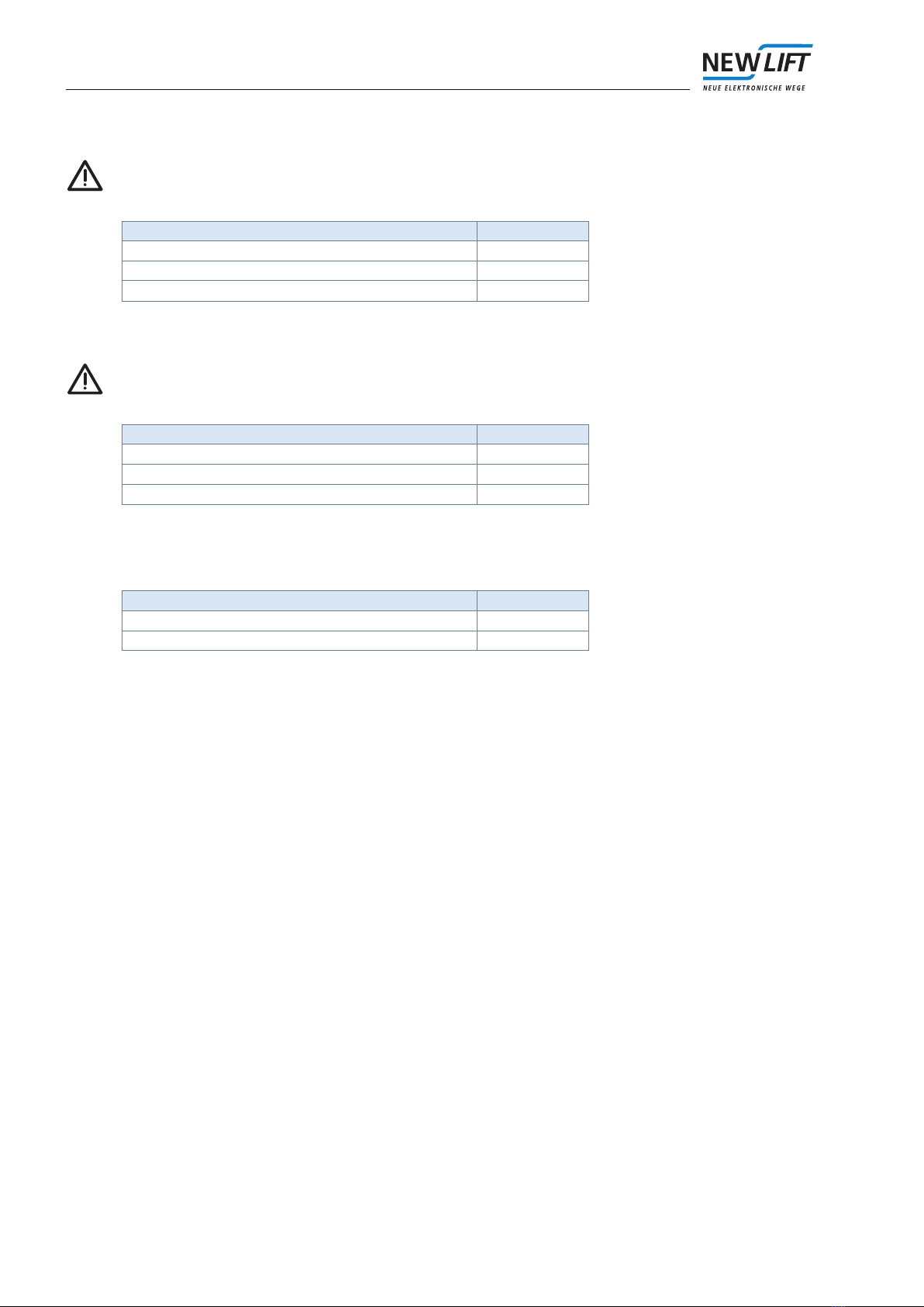
FST-2XTs jumper J1: encoder - incremental / CAN Open LIFT
Function J1
Incremental 24V 1-2
CANopen Lift ground 2-3
FST-2XT and FST-2XTs jumper J2: load measurement inputs
Function J2
Switched GND for load measurement inputs 1-2
Switched +24 V for load measurement inputs 2-3
FST-2XTs jumper J3: encoder - incremental / CAN Open LIFT
Function J3
Incremental 5V 1-2
CANopen Lift 24V 2-3
FST-2XTs jumper J4: encoder - incremental / CAN Open LIFT
Function J4
Incremental track A 1-2
CANopen Lift channel L 2-3
FST-2XTs jumper J5: encoder - incremental / CAN Open LIFT
Function J5
Incremental track A negated 1-2
CANopen Lift channel H 2-3
FST-2XT and FST-2XTs jumper J90: shielding X9
This jumper is in the open position on delivery. Set only after consulting with NEW LIFT.
The shielding of service-PC cable X9 is connected to PE or GND potential with J90.
Function J90
Shielding of the connecting cable on PE 1-2
Shielding of the connecting cable on GND 2-3
Shielding of the connecting cable insulated open
FST jumpers
Generalsafetyregulations
10 ManualforreplacingFST-2swithFST-2XTs
FST-2XT and FST-2XTs jumper J100: shielding X43
This jumper is in the open position on delivery. Set only after consulting with NEW LIFT.
The shielding of modem cable X10 is connected to PE or GND potential with J100.
Function J100
Shielding of the connecting cable on PE 1-2
Shielding of the connecting cable on GND 2-3
Shielding of the connecting cable insulated open
FST-2XT and FST-2XTs jumper J110: shielding X11
This jumper is in the open position on delivery. Set only after consulting with NEW LIFT.
The shielding of DCP cable X11 is connected to PE or GND potential with J110.
Function J110
Shielding of the connecting cable on PE 1-2
Shielding of the connecting cable on GND 2-3
Shielding of the connecting cable insulated open
FST-2XT and FST-2XTs J120: shielding X12
The shielding of encoder cable X12 is connected to PE or GND potential with J120.
Function J120
Shielding rotary encoder cable on PE 1-2
Shielding rotary encoder cable on GND 2-3
Este manual sirve para los siguientes modelos
1
Tabla de contenidos
Otros manuales de Controladores de New lift


