Loctite CL10 Manual de usuario

EQUIPMENT
Operation Manual
Intensity%
Time S
CL10 Single LED Controller
ItemNo. 1514636
SET
LoctiteCL10 Single LED Controller
Item # 1514636

2
Contents
............................................................................................................................................................................1
Contents............................................................................................................................................................2
1 Caution...........................................................................................................................................................3
1.1 Safety Instruction...............................................................................................................................4
1.2 Out of Box Inspection........................................................................................................................4
1.3 Items Supplied ...................................................................................................................................4
2 Overview........................................................................................................................................................5
3 Technical Data..............................................................................................................................................5
4 Installation ....................................................................................................................................................6
4.1 Capacity..................................................................................................................................................6
4.2 Dimension...............................................................................................................................................6
4.3 Caution................................................................................................................................................7
4.4 Installation Flow.................................................................................................................................7
5 Controller button and Operating...........................................................................................................8
5.1 Component name and function .......................................................................................................8
5.2 Button and Display Instruction ...........................................................................................................9
5.2.1 Button Instruction...............................................................................................................................9
5.2.2 Display instruction..............................................................................................................................9
5.3 Operating............................................................................................................................................9
5.3.1 Startup............................................................................................................................................9
5.3.2 Starting Controller.......................................................................................................................10
5.3.3 Working Mode.............................................................................................................................10
5.4 Parameter Setting............................................................................................................................10
5.4.1 Intensity Setting...........................................................................................................................10
5.4.2 Time Setting ................................................................................................................................10
5.5 Working mode setting.....................................................................................................................11
5.6 Working Temperature.....................................................................................................................11
5.7 LED Head Unit and Foot Switch ...................................................................................................11
6 Shutdown...............................................................................................................................................12
7 Troubleshooting....................................................................................................................................13
8 Replacement Parts...............................................................................................................................14
9 WARRANTY..........................................................................................................................................15

3
1 Caution
Info:
Warning instructions in this manual and on labels are classified and described
below.
WARNING: This means that possible death or serious
injury to the operator may result if these instructions are
ignored and the equipment handled incorrectly.
Forbidden:This symbol means that the instruction
describes prohibited item or action.
ELECTRICAL EQUIPMENT
This symbol means that possible serious injury by high
voltage.
Heating:This symbol means possible serious injury by
high temperatures.
Info
Ultraviolet radiation warning:This symbol means that
possible serious injury by Ultraviolet radiation.
4
1.1 Safety Instruction
Forbidden
Disassembly and modification is prohibited.
Discontinue use if power cable is frayed or damaged.
Should an abnormal condition occur such as smoking, abnormal smell or
noise, turn off the power immediately and disconnect the power cable from
the AC outlet.
When internal inspection or repair is needed, contact the selling agent or
Henkel.
Warning
Disassembly and modification is prohibited.
Make sure that the power voltage in use complies with specifications.
Disconnect the power supply after finishing work.
Please hold power plug when unplugging the power cable.
Do not allow liquid to enter the equipment.
Disconnect the power supply before cleaning the equipment. Do not use an
organic solvent to clean the cabinet.
In case of an abnormal condition, stop using the equipment immediately.
1.2 Out of Box Inspection
Open Loctite® CL10 Single LED Controller package carefully and check if any
components were damaged during shipment. Please inform carrier if damage has
occurred. Any claims for shipping damage must be made to the carrier and inform
supplier immediately.
1.3 Items Supplied
1514636 Loctite® CL10 Single LED Controller x1
97201 Foot Switch x1
Power Cable x1
Make sure to read these “safety Instructions”carefully before
starting to use the equipment and observe them during operation.
Please familiarize yourself with warning instructions and labels.

5
2 Overview
Loctite® CL10 Single LED Controller is a UV light source that emits a spot of
light at a wavelength of 365 or 405nm for use in adhesive Light Cure bonding
applications.
Advantage:
1. Over 20,000 working hours.
2. No IR emission resulting in low temperature curing. Will not damage
parts due to heat emission.
3. Up to 90% energy savings, compared with mercury arc lamps.
4. Small, LED head for hand held or fixed fixture applications.
5. Foot switch actuated or PLC remote control.
6. Timed mode or manual cycling.
7. Low maintenance cost.
3 Technical Data
Type CL10 Single LED Controller
Timer Intensity:0~100%,Timer:0.1~999.9s
MODE Manual Intensity (0~100%),Timer: Manual Control
Power Suppy AC 100~240V 50/60Hz
Power Consumption 15W
Cooling Method Natural Cooling
Temperature Range Operating:+5~40℃,Storage: -15~+65℃
Weight 0.6Kg
Wavelength 365nm, 405nm
6
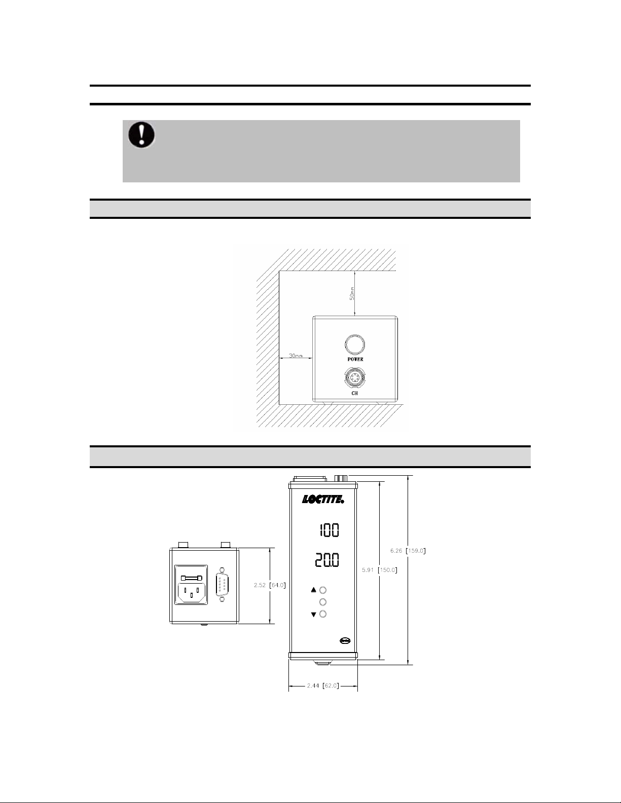
4 Installation
4.1 Capacity
Min .space required for the equipment
4.2 Dimension
Intensity %
Time S
CL10 Single LED Controller
Item No. 1514636
SET
XS-1 AC100~240V 50/60Hz
FUSE:2AMP 250VAC
Please check the unit for any mechanical defects. If there is any shipping
damage do not install or use the equipment and immediately contact the
shipping company and supplier.

7
4.3 Caution
To prevent heat damage, set the unit horizontally on a level
surface. Failure to position the unit properly may cause damage.
Avoid placing next to high voltage equipment or next to a heat
source.
Make sure nothing is placed on the power cable.
4.4Installation Flow
1. Place the controller horizontally on a level surface.
2. Connect power cable to controller using supplied power cable.
3. There is one LED head connector labeled <CH> under the power
button, connect LED head to <CH>.
4. Connect foot switch or PLC(optional)to connector labeled <XS-1>
Caution:Depress power switch to turn on the LED head, press
again to turn off. When using a PLC or extension cable, 0V means
the LED head is working.

8
5 Controller button and Operating
5.1 Component name and function
1. Power Switch:Power On/Off
2. LED head connector
3. Intensity display:Intensity setting data and information will be
shown here, easy to read and edit.
4. Time display:Time setting data and information will be shown
here, easy to read and edit.
5. Up arrow button
6. SET Button:Confirm or enter menu.
7. Down arrow button
8. Power cable connector
9. Control port:LED head control signal input.
Intensity %
Time S
CL10 Single LED Controller
Item No. 1514636
SET
POWER
CH
XS-1 AC100~240V 50/60Hz
FUSE:2AMP 250VAC

9
5.2 Button and Display Instruction
5.2.1 Button Instruction
Arrow buttons:Edit settings
SET
5.2.2 Display instruction
Intensity %
Time S
5.3 Operating
5.3.1 Startup
Power
Power Switch:Power On/Off.
SET Button:Confirm or enter menu.
Intensity data information
Time data i
nformation
Warning
Please place this equipment in a stable space.
Avoid placing next to high voltage machinery.
Please do not block ventilation holes.
Do not expose to flammable gas.
Do not use in high temperatures or extreme cold.
To avoid electric shock, disconnect equipment from
electrical supply before servicing.
Caution
To avoid button damage, do not press buttons with high
force.
Prevent metallic foreign matter from entering the LED head
connector, may cause short, damage and fire.
Don’t connect any non LED head cable to connector; it may
cause errors and damage.

10
5.3.2 Starting Controller
After finishing installation, plug in power cable, then press . The red LED
light inside the button will turn on when the unit is powered.
5.3.3 Working Mode
If the LED head is plugged in, the controller will automatically enter Working
Mode.
5.4 Parameter Setting
5.4.1 Intensity Setting
1. Enter working mode.
2 Press and hold up button to set intensity. (Intensity data will
flash when up button is released).
3 Press up button or down button to adjust intensity.
4 Press SET twice to confirm and save.
5.4.2 Time Setting
1. Enter working mode.
2. Press and hold down button to edit time. (Time data will be
flashing).
3. Press up button or down button to change intensity
value.
4. Press SET to confirm and move to next unit.
5. Press SET twice to confirm and save when finished with last unit’s
setting.
Power
Power
Caution
All settings should be adjusted in working mode!
Otros manuales para CL10
1
Tabla de contenidos
Otros manuales de Controladores de Loctite

Loctite
Loctite 1461974 Manual de usuario

Loctite
Loctite 2257357 Manual de usuario

Loctite
Loctite Single CureJet Manual de usuario

Loctite
Loctite 98521 Manual de usuario

Loctite
Loctite CL10 Manual de usuario

Loctite
Loctite EQ CL42 Manual de usuario

Loctite
Loctite 97102 Manual de usuario

Loctite
Loctite 97152 Manual de usuario


