LLG pH meter 7 Manual de usuario
LLG-pH METER 7
Art.No. 6.263 600
Thank you very much for purchasing this LLG-pH METER 7.
Please read the following instructions carefully and always keep
this manual within easy reach.
LABWARE
®
INSTRUCTION MANUAL
INSTRUCTION MANUAL UK

LABWARE
®
2
1 Preface 2
2 Installation 3
3 Instruction 4
4 Measurement process 7
5 TechnicalSpecications 9
6 Self-diagnostic 10
7 Maintenance 12
8 Attention 13
WARRANTY REPLACEMENT 15
pH meter is a kind of wide used general
instrument in many different applications.
A typical pH meter consists of two parts: a
measuring probe and an electronic meter.
The measuring probe includes glass probe
and reference electrode, called pH electrode.
Today pH electrode normally has a built-
in temperature sensor, calls 3 in 1 pH
electrode.
1. Preface
Measuring principal:
E=E0-(2.3 RT/nF)*pH............................................................Nernst equation
E
measured potential (mV)
E0
standard electrode’s potential (mV)
R
the ideal gas constant (8.3144 J/K)
T
the temperature in Kelvin (K)
nthe number of moles of electrons transferred in the cell reaction or half-
reaction (H+=1)
FFaraday’s constant (96485 C mol-1)

INSTRUCTION MANUAL
3
Please instruction manual carefully before
using this instrument: read this
• Check the meter and the accessories
according to the enclosed packing list.
• Unpack the meter, connect it with the
power line in the box, plug the power line
to the local power supply. The display
screen should be lighted, press ‘ ’ key,
the meter is ready for use.
• If the user needed to transfer data to a
computer while measuring, please connect
a cable between the computer and the
RS232 socket of the meter before starting
measurement.
Note:
The meter could be switched on again
in 24 hours by touching any place on
the screen (3 seconds) if the meter
is switched off by pressing the red
“off” key on the screen. Unplug the
power and plug it again to switch the
meter on if the meter has not been
used for more than 24 hours. This is
for protecting the meter and energy
saving.
2. Installation
!
!
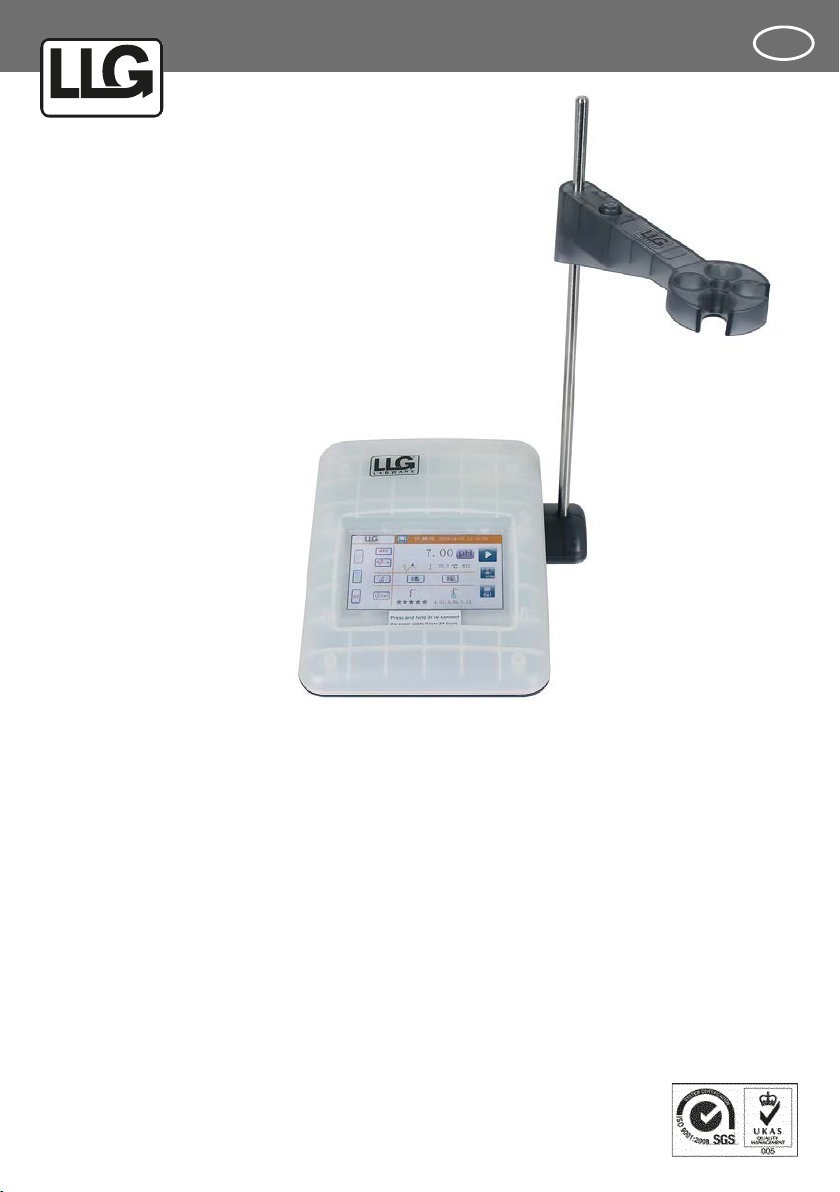
Fig. a is the assembly of parts
Fig. b shows the meter ready for use
Installation:
Put the electrode stand base under the
pH meter, mount the base and the meter
using the supplied screw. Press the button
on the electrode stand arm to install it.
Attention:
Keeping the supplied protective
cover on the device while operating
it may affect the functioning of the
touch display. For proper results, we
recommend to remove the protective
cover.
Fig. 1:
The illustration of
pH meter installation

LABWARE
®
4
LABWARE
®
3. Instruction
The display of this instrument is 5” TFT
color LCD touch screen. The operator
can touch any icon on the screen except
the measurement reading to operate the
instrument. Fig. 2.
Fig. 2:
The illustration of the
main screen of the
pH meter
1. The main measurement screen and functional keys
1.1 Area A
System and measurement settings of the instrument
Key for date and time
adjustment. Screen lightness adjustment.
Switch off key. Press this key to switch off the instrument.
MTC Manual temperature compensation. For MTC temperature setting
End point selection. A- auto endpoint. M- manual endpoint.
Online data transfer. Press this icon, user can transfer measurement result to PC
or printer. For data transfer to PC, please follow the instruction in the software
package.
Electrode calibration reminder. Press this key to input the time, day, to remind the
user calibrate the electrode on time.

INSTRUCTION MANUAL
5
1.2 Area B
Measurement Result Display
Measurement result unit., press it to make an alternate display.
A M Endpoint. A-automatic, M-manual.
Temperature in Celsius degree.
1.3 Area C
Database
Press this icon for data in database transfer.
Press this icon for review data in database.
1.4 Area D
The electrode status and the buffer solution
The electrode status. 5 … 3 star is the minimum requirement for good
measurement. Press it to review the electrode calibration data.
4.01,7.00,9.21
The buffer solutions selected for the electrode calibration. Press it to view
the electrode calibration data.

LABWARE
®
6
1.5 Area E
Operation keys
Press it to start a measurement or make a conrmation.
Press to end a measurement process manually.
Press to save current reading.
The current datum has been saved.
Press to start the calibration process.
1.6 Area F
Navigation bar
The date and time set by the operator.
PC or Printer. The operator selected.
LABWARE
®
Press this logo, the user can view the information of this meter, such as
S/N, software version, restore the factory settings and the instruction
menu.
Restore factory settings: all the settings will be replaced by the default
settings.
Item Default setting Item Default setting
MTC 25.0 °C Database remain
Endpoint mode auto Electrode calibration
curve 100 %
Data transfer Off Buffer solutions Europe standard
Calibration Reminder None Screen brightness Medium
INSTRUCTION MANUAL
7
4. Measurement process
It’s recommended to perform an electrode
calibration before measuring a sample. If
the electrode is calibrated in short time,
the sample measurement can be conducted
directly.
If the electrode without temperature
compensation is used, “MTC” will be
displayed on the main screen, press „ ”
on the main screen, user can set up the
calibration buffer solution temperature.
If a 3-in-1 electrode is being used, or a
temperature electrode is used at the same
time, “ATC” will be displayed on the main
screen and the calibration buffer solution
temperature will be measured automatically.
Press the „ ” on the main screen, select
one of the standard buffer solutions groups
built-in. The selected standard buffer
solution group must match the buffer
solution group actually used.
Press „ “ on the main screen, the
calibration window pop-up, Fig. 3, put the
electrode in the rst buffer solution,
press „ “to start the calibration.
When the endpoint reached, take the
electrode out and wash it with DI water, dry
it, put it in the second buffer solution for
second point calibration, same procedure for
the third point calibration.
The calibration data will be stored in the
database after press the return key.
This icon means the calibration result
meets requirement
Means the result is not under satisfaction.
Notice:
• During the calibration process, if the red
wave line is shining, means the calibration
is going on, if press” return ” at this time,
the calibration process will stop and go
back to the main screen.
• Calibration buffer solutions selection:
normally, the pH values of the selected
calibration buffer solutions are similar
to the pH of the sample solutions to be
tested.
1. Calibration

LABWARE
®
8
Fig. 3:
The illustration
of the electrode
calibration
Wash the electrode with DI water, dry it, put
it in the sample solution, stir the solution
with electrode slightly.
Press key on the screen starting the
measurement. Press on the screen after
the endpoint reached, saving measurement
result to database. Fig. 4.
2. Measurement
Fig. 4:
The illustration of
measurement

INSTRUCTION MANUAL
9
5.TechnicalSpecications
Model
Parameter
ph-Meter 7
Measurement mode pH/mV
pH range (pH) -2.00 to 20.00
Resolution (pH) 0.01
Accuracy (pH) ± 0.01
mV range (mV) -2000 to 2000
Resolution (mV) 1
Accuracy (mV) ± 1
Temperature range (°C) MTC: -5.0 to 105.0 °C
ATC: -5.0 to 105.0 °C
Temperature Accuracy (°C) ± 0,5 °C
Calibration 3 predened pH buffer groups, automatic buffer
recognition
Database 500 groups measuring data
Data output RS232, Printer (optional),
IS-Link
Display 5.0˝ color, touch screen,
Resolution 480*720
Power 9V DC/1A
pH Input BNC, Impedance>10 e+12 Ω
Temperature input NTC 30 KΩ
Order No. 6.263 600
Conguration IS126 Meter,YE203 electrode, Electrode stand, Protective
cover

LABWARE
®
10
6. Self-diagnostic
During the instrument operation process,
some signs might appear on the main
screen, this is the information of the
instrument self-diagnostic, which will help
you to nd out some problems of the
instrument or the electrode you are using.
1. Electrode Status:
offset
slope
< 15 mV 15 mV ≤ offset ≤
35 mV > 35 mV
95%≤slope≤105%
90%≤slope≤95%
85%≤slope≤90%
slope>105%
slope<85%
Este manual sirve para los siguientes modelos
1
Tabla de contenidos
Otros manuales de Instrumento de medición de LLG


Manuales populares de Instrumento de medición de otras marcas


Endress+Hauser
Endress+Hauser Proline Promag 50 Especificaciones técnicas

Siemens
Siemens SITRANS F Coriolis FCT030 Manual de lista de piezas

KLINGER
KLINGER CMF V Series Manual de usuario

EXFO
EXFO FTB-2 Manual de operación y mantenimiento

Keysight
Keysight M8290A Manual de usuario

ADTEK
ADTEK MW-5 Manual de usuario