
LLG LLG-uniSPEC 2 Manual de usuario

LLG-uniSPEC 2
Please read the User Manual carefully before use, and follow all
operating and safety instructions!
LABWARE
®
INSTRUCTION MANUAL
INSTRUCTION MANUAL UK

LABWARE
®
2
1. Preface
1. Safety ........................................ 3
2. General ....................................... 3
3. Electrical ..................................... 4
4. Warning ...................................... 4
5. Performance ................................... 4
6. Radio Interference ............................... 4
2. Introduction of the Instrument
1. Brief Introduction of the Instrument................... 5
2. Working Principle ................................ 6
3. Structure...................................... 7
4. Unpacking Instructions ............................ 7
5. Specications................................... 8
3. Install Instrument
1. Environment Required............................. 9
2. Voltage Conrmation ............................. 9
3. Installation ....................................10
4 Operation Introduction
1. Software Structure ...............................11
1.1. Menu Tree ................................11
1.2. Firmware Functions ........................ 12
1.2.1 Basic Mode .............................. 12
1.2.2 Quantitative.............................. 12
1.2.3 Kinetics ................................. 12
1.2.4 Setup .................................. 12
2. Basic Operation ................................ 12
2.1 Choose Photometric Mode .................... 12
2.2 Set Wavelength ........................... 12
2.3 Set Parameters ........................... 12
2.4 Set the position of auto-cell holder.............. 12
2.5 Delete the Input Value ...................... 12
2.6 Delete the test result and stored data ........... 12
2.7 Calibrate 100%T/0Abs....................... 12
2.8 Measure Samples .......................... 12
2.9 Print the test result ........................ 12
3. Preparation before test ........................... 13
3.1 Switch on the instrument and begin
the system self-test ........................ 13
3.2 Pre-warm ............................... 13
3.3 Check the cuvettes......................... 13
4. Measurement.................................. 13
4.1 Basic Mode .............................. 13

INSTRUCTION MANUAL
3
4.2 Quantitative.............................. 15
4.3 Kinetics ................................. 21
4.4 Setup ...................................24
4.4.1 Power On/O D2 Lamp..................24
4.4.2 Power On/O W Lamp ................. 25
4.4.3 Set Date and time .................... 25
4.4.4 Calibrate Dark Current ................. 26
4.4.5 Wavelength Calibration ................ 26
4.4.6 Input the lamps changing Wavelength Point .. 27
4.4.7 Reload Default....................... 26
4.4.8 Version ............................ 28
5 Instrument Maintenance
1. Daily Maintenance .............................. 28
2. Trouble shooting ............................... 29
3. Spare part Replacement .......................... 30
1. Preface
The safety statements in this manual comply
with the requirements of the HEALTH AND
SAFETY AT WORK ACT, 1974.
Read the following before installing and
using the instrument and its accessories.
This instrument should be operated by
appropriate laboratory technicians.
1. Safety
The apparatus described in this manual is
designed to be used by properly trained
personnel in a suitable equipped laboratory.
For the correct and safe use of this
apparatus it is essential that laboratory
personnel follow generally accepted
safe procedures in addition to the safety
precautions called for in this manual.
The covers on this instrument may be
removed for servicing. However, the inside
of the power supply unit is a hazardous area
and its cover should not be removed under
any circumstances. There are no serviceable
components inside this power supply unit.
For this instrument, avoid touching the high
voltage power supply at all times.
Some of the chemicals used in
spectrophotometry are corrosive and/
or inammable and samples may be
radioactive, toxic, or potentially infective.
Care should be taken to follow the normal
laboratory procedures for handling chemicals
and samples.
2. General

LABWARE
®
4
LABWARE
®
Before switching on the apparatus, make
sure it is set to the voltage of the local
power supply (see Installation).
The power cord shall be inserted in a socket
provided with a protective earth contact.
The protective action must not be negated
by the use of an extension cord without a
protective conductor.
3. Electrical
Any interruption of the protective
conductor inside or outside the apparatus
or disconnection of the protective earth
terminal is likely to make the apparatus
dangerous. Intentional interruption is
prohibited.
Whenever it is likely that the protection has
been impaired, the apparatus shall be made
inoperative and be secured against any
unintended operation.
Note
NEVER touch or handle the power supply on
this instrument due to the high voltage!
The protection is likely to be impaired if, for
example, the apparatus
• Shows visible damage
• Fails to perform the intended
measurements
• Has been subjected to prolonged storage
under unfavorable conditions
• Has been subjected to severe transport
stresses
4. Warning
To ensure that the instrument is working
within its specication, especially when
making measurements of an important
nature, carry out performance checks with
particular reference to wavelength and
absorbance accuracy. Performance checks
are detailed in this manual.
5. Performance
For compliance with the EMC standards
referred to in the EC Declaration of
Conformity, it is necessary that only shielded
cables supplied by us are used when
connecting the instrument to computers and
accessories.
6. Radio Interference

INSTRUCTION MANUAL
5
2. Introduction of the Instrument
1. Brief Introduction of the Instrument This
instrument is a single beam, general purpose
instrument designed to meet the needs of
the Conventional Laboratory, This instrument
is ideal for various applications, such as:
Chemistry, Biochemistry, Petrochemistry,
Environmental Protection, Food and
Beverage Labs, Water and Waste Water
Labs and other elds of quality control and
research.
This instrument incorporates a 128 x 64 dots
matrix LCD display for photometric results,
easy operation and wavelength range of
190 nm to 1100 nm. This instrument is
ideal for measurements in the visible and
ultraviolet wavelength region of the
electromagnetic spectrum.
1. Brief Introduction of the Instrument
Fig Front View
Fig Control Panel

LABWARE
®
6
2. Working Principle
Dierent matter has dierent but special
absorbance wavelength point. Also, when at
the xed wavelength point, the absorbance
has some relation to the substance’s (Always
transparent Solution) concentration and its
thickness. The relation can be concluded
as the following Formula which is called
Lambert-Beer Law.
T= I/Io
A=KCL= -log I/Io
A Absorbance
C Concentration of the Solution
K Absorbance Coecient of the
Solution
L The length of the Solution in
the light path
I The intensity of the light
focused on the A/D after it
permeates the solution to be
measured.
IoThe intensity of the light
focused on the A/D before it
permeates the solution.
Note:
When test, the solvent is usually taken as
the Reference Solution and its Transmittance
is considered as 100 %T. While the
Transmittance of the sample to be tested is a
relative value which is got comparing to that
of the Reference.
Fig Back View Air inlet Fuse Parallel port
USB portPower socketPower switchFan
INSTRUCTION MANUAL
7
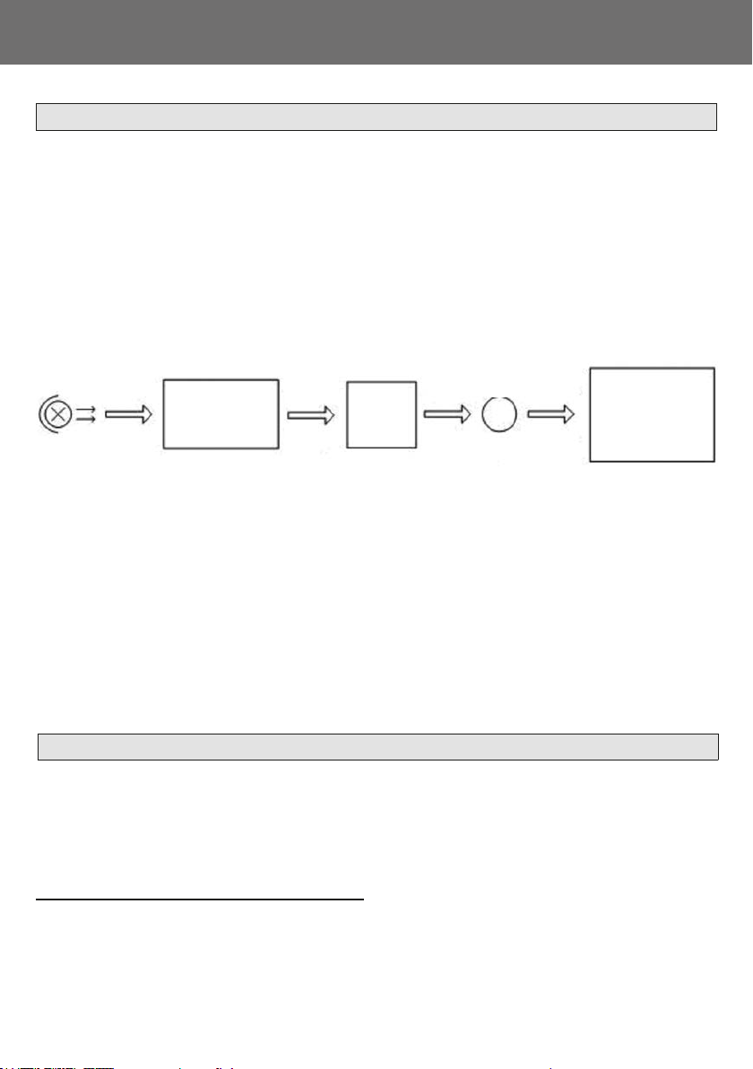
3. Structure
The spectrophotometer consists of ve
parts:
1. Halogen or deuterium lamps to supply the
light
2. A Monochromator to isolate the
wavelength of interest and eliminate the
unwanted second order radiation
3. A sample compartment to accommodate
the sample solution
4. Detector to receive the transmitted light
and convert it to an electrical signal; and
A digital display to indicate absorbance or
transmittance. The block diagram below
illustrates the relationship between these
parts.
Fig Block diagram for the Spectrophotometer
Light
Source
Monochromator Sample
Compartment
Detector Process and
Display
In your spectrophotometer, light from the
lamp is focused on the entrance slit of the
monochromator where the collimating mirror
directs the beam onto the grating. The
grating disperses the light beam to produce
the spectrum, a portion of which is focused
on the exit slit of the monochromator by a
collimating mirror. From here the beam is
passed to a sample compartment through
one of the lters, which helps to eliminate
unwanted second order radiation from the
diraction grating. Upon leaving the sample
compartment, the beam is passed to the
silicon photodiode detector and causes the
detector to produce an electrical signal that
is displayed on the digital display.
4. Unpacking Instructions
Carefully unpack the contents and check the
materials against the following packing list to
ensure that you have received everything in
good condition.
Packing List
Description Quantity
Spectrophotometer................................. 1
Power Cord............................................ 1
Glass Cuvettes ........................... 1 Set of 4
Quartz Cuvettes ......................... 1 Set of 2
Operation Manual ................................... 1
Note:
The Printer and Auto-cell Holder mentioned
in this manual are all optional accessories,
they do not come standard with the
instrument.

LABWARE
®
8
5. Specications
Model LLG-uniSpec 2
Wavelength Range 190-1100 nm
Band Width 2 nm
Wavelength Accuracy ± 0.5 nm
Wavelength Repeatability 0.3 nm
Wavelength Setting Auto
Photometric Accuracy ±0.5 % T
Photometric Repeatability 0.3 % T
Photometric Display Range 0-200 % T, -0.3-3.0 A
Stability 0.002 A/h @ 500 nm
Stray Light ≤0.05 % T @ 220 nm, 360 nm
Data Output Port USB
Printer Port Parallel Port
Display 128 x 64 Dots LCD
Lamps Deuterium Lamp & Tungsten Halogen Lamp
Detector Silicon Photodiode
Power Requirement 220 V/50 Hz or 110 V/60 Hz
Dimension (L x W x H) 460 x 380 x 180mm
Net Weight 18 kg

INSTRUCTION MANUAL
9
3. Install Instrument
To ensure the best performance, the
following conditions are required:
• The best working temperature range is
16-30 °C and the humidity is 45-80 %.
• Keep it as far as possible away from the
strong magnetic or electrical elds or any
electrical device that may generate high-
frequency elds.
• Set the unit up in an area that is free
of dust, corrosive gases and strong
vibrations.
• Remove any obstructions or materials
that could hinder the ow of air under and
around the instrument.
• The power requirement is
220±22V@50±1Hz or 110±11V@60±1
Hz.
• Use the appropriate power cord and plug
into a grounded outlet.
• If the local voltage is not stable enough, a
manostat is required.
• Be away from direct sunlight
1. Environment Required
Be sure to set the instrument’s Voltage Switch at your local power
supply, or severe damage may occur! The Voltage Switch is on the
bottom of the instrument.
2. Voltage Conrmation
e.g.: If your local Voltage is 220V, you
should set the Voltage Switch at the
following status.
If your local Voltage is 110V, you should stir
the switch to the Left way by nger, so that
it can be set at 110V.

LABWARE
®
10
Step 1: Check the packing list
Unpack the contents, check the materials
with the Packing List. Any damage or Lost
found, please contact us or the local dealer.
Step 2: Position
Place the instrument on the stable table
carefully.
Step 3: Install printer (Optional)
Make sure the printer is power o; link
the printer’s data cable to the instrument’s
parallel port.
Step 4: Link the power cord
Make sure the instrument’s power switch
is in the O condition, link the power cord
to the instrument and insert another end in
the socket provided with a protective earth
contact.
Step 5: Switch on the power
Check again, make sure that all the links are
right. Switch on the power. The instrument
can be used to measure after self-test and
pre-warm.
3. Installation
Tabla de contenidos
Otros manuales de Instrumento de medición de LLG


Manuales populares de Instrumento de medición de otras marcas


Endress+Hauser
Endress+Hauser Proline Promag 50 Especificaciones técnicas

Siemens
Siemens SITRANS F Coriolis FCT030 Manual de lista de piezas

KLINGER
KLINGER CMF V Series Manual de usuario

EXFO
EXFO FTB-2 Manual de operación y mantenimiento

Keysight
Keysight M8290A Manual de usuario

ADTEK
ADTEK MW-5 Manual de usuario