Kudo3D Bean Manual de usuario

Kudo3DBeanUserManual
Ver.1.0
1of14
Bean User Manual
Revision 1.0
Copyright © 2018 by Kudo3D. This material may be distributed only subject to the terms and conditions set forth
in the Creative Commons Attribution-NonCommercial-NoDerivatives 4.0 International License or later. The latest
version is presently available at http://creativecommons.org/licenses/by-nc-nd/4.0/.

Kudo3DBeanUserManual
Ver.1.0
2of14
Table of Contents
I. Product Introduction..................................................................................................................................3
II. Standard Package Materials and Tools.............................................................................................5
III. Setting up the printer...............................................................................................................................5
IV. Printing Flow...............................................................................................................................................5
V. Z zero Calibration.......................................................................................................................................7
VI. Linear Guide Calibration........................................................................................................................8
VII. Teflon Film Replacement......................................................................................................................8
VIII. Software Tool Chain..............................................................................................................................9
IX. FAQ..............................................................................................................................................................12

Kudo3DBeanUserManual
Ver.1.0
3of14
I. Product Introduction
Foot Print
Build Volume
XY Resolution
Maximum Z Resolution
Speed
Weight
Light Source
Pattern Generation
Printout Uniformity
VAT
Software
Wireless Printing
Resins
Zero Calibration
System Requirement
Z motion
Voltage
20 x 20 x 40 cm
6.8 x 12 x 16 cm
47 μm
10 μm
10 - 20 mm /hr
15 lb / 6.5Kg
60W 405nm LED
2K LCD panel
> 95% for feature sizes >1.5mm
PSP-D (Drum type PSP container)
Web-based
Via Wi-Fi repeater or router
3rd party compatible
Pre-calibrated zero with an optical sensor
Windows, Mac, Linux or any portable devices
Patent pending anti-wobbling mechanism (AWM)
100 – 240 V
1. Cover
2. Build Platform
3. Resin Container
4. Linear Guide
5. Ethernet Jack
6. Power Jack
7. Power Button

Kudo3DBeanUserManual
Ver.1.0
4of14
WARNING
Bean should be operated in a clean open area with air circulation at a temperature about 25 degree
Celsius to prevent overheating.
Do not clean the acrylic cover with IPA
The back of Bean should be at least 5cm sway from the wall
Do not touch the LCD panel directly with your fingers. LCD is extremely sensitive to the electrostatic
discharge.
You may consider using thin black tape to seal the gap between the LCD and the rim of the opening to
prevent dripped resin entering the gap.
When moving the linear stage down, the platform must be attached. The carrier is tightened to prevent
horizontal swinging so it needs the weight of the platform to move down smoothly.
Must use dry lubricant to lubricate the linear screw and guide
CE/FCC Notice
For EN 55022: 2010 warning: This is a class A product. In a domestic environment this product may
cause radio interference in which case the user may be required to take adequate measures.
For EN 55032: 2012 warning: This equipment is compliant with Class A of CISPR 32. In a residential
environment this equipment may cause radio interference.
For EN 55032: 2015 warning: Operation of this equipment in a residential environment could cause radio
interference.

Kudo3DBeanUserManual
Ver.1.0
5of14
II. Standard Package Materials and Tools
1. Printer
Constructed mostly with metal
Easy to clean up and maintain
Immune from the attack of resin
Patent pending anti-wobbling mechanism
2. Acrylic Cover
3. Accessories & Tool
A. FEP film x 5 pcs
B. LAN cable
C. Wi-Fi repeater
D. Build platform holder
E. Gloves
F. Black rubber scraper
G. Funnel
H. Plastic container
I. Screws and studs for Teflon film replacement
J. Metal scraper
III. Setting up the printer
Level the printer with the 4 legs under the printer.
You can use your PC, Mac, Tablet or smart phone to control or monitor the printer. In order to
communicate with your printer, your devices must be on the same local area network (LAN)
environment. You would need a router or a repeater to connect the printer in the network. An IP
address is assigned to the printer by your router automatically. Once you press the Print button, you
can remove these devices without interrupting the printing.
Inspect and make sure the LCD surface and the lower surface of the Teflon film are clean and there
are no dusts between these two surfaces.
IV. Printing Flow
1. Design or download a digital model.
2. If the model is not in the stl format, please export or convert it into stl.
3. Use Netfabb basic to check if there is any mesh error and repair it with the red-cross button.
Please refer to https://www.youtube.com/watch?v=2QRvS9xdNzw for installing Netfabb basic.
4. If Netfabb basic fails to repair the stl, please use Windows 10 3D Builder or Netfabb online to repair.
5. If necessary, please hollow the model with Autodesk Meshmixer and check the mesh error again.
6. Import the model to support generation software to add supports and export it in stl format.
7. Import this stl model with supports to a slicing software to slice the model into .png layers.

Kudo3DBeanUserManual
Ver.1.0
6of14
8. Wrap the slices into a .zip file.
9. Open the Safari or Chrome browser on your PC or other devices.
10. Go to http://Kudo3D.local/ to access the Bean controlling software.
11. Press the “Control” Tab and move the platform to Platform-Position z = 10mm with the arrow key.
12. Pour in enough resin so that the build platform barely touches the surface of the resin. For printing larger
models, you may need to add more resin during printing.
13. Lower the platform to Platform-Position z = 0 or press the “Home” button.
14. Upload the .zip slices to your printer using the “Upload” button at the bottom of the “Files” pane.
15. Press the “Print” tab. Press the “Basic” mode and select the material to be used. Default parameters will
be loaded.
16. If you would like to use 3
rd
party resins, please press “Advanced” mode. Press the “Advanced Settings”
below and you will be able to input your own parameters. Remember to save the new parameters to
a .csv file so next time you can use them again.
17. Alternatively, you can download an existing printing parameter .csv file and modify it in excel. Upload it to
the printer.
18. Make sure the “Begin layer no” starts from 1 and the Slice Thickness is correct.
19. Press the “Print” button.
20. For big models that do not have proven parameters, we suggest monitoring the printing process for the
first 10mm until you are sure that model does not drop.
You can “Pause” the printing process and press the “Check” button to lift the platform up to confirm. If
everything is fine, press “Resume” to restart printing.
Note: If there is a large separation force, you will see the vat gets lifted slightly and then drops. This is a
peeling movement to reduce the separation force. It improves the surface quality, especially for larger
models.
21. After the print is completed, use the rubber scraper provided to drive the resin on the top back to the
container gently. Avoid resin dripping on the printer.
22. Loosen the black hand-knob on the platform arm and remove the build platform slowly. Some resin could
hide inside the model, make sure it drips back to the container. Use the rubber scraper again to remove
the residual resin on the platform.
23. Prepare two plastic containers filled with Isopropyl Alcohol (IPA). One may hold older / recycled IPA while
the other must hold cleaner IPA. Use the hanger provided to soak the model in the old IPA for 2 minutes

Kudo3DBeanUserManual
Ver.1.0
7of14
and then in the cleaner IPA for another 2 minutes. The actual soaking time depends on the resin used
and the model structure. If necessary, use a squeegee bottle filled with clean IPA to do the last cleaning.
24. Leave or gently blow the model until it dries.
25. Remove the model from the platform with a blade or a metal scraper.
WARNING:
Be careful not to cut your fingers.
26. Post cure your model under a UV lamp or sun. Usually, 30 minutes under an UV lamp is enough. Under
the sunshine, you would need to rotate the model every 15 minutes for an hour. You can soak the model
in the water to block the oxygen to accelerate the post curing.
27. Use a cutter to remove the supports.
28. You may need to polish the surface with supports.
V. Z zero Calibration
Normally, you do not need to calibrate Z zero. You need to calibrate the z zero only when a new platform is
used for the first time. Please refer to the video. https://youtu.be/-NPw4VYMV7M
1. Loosen the four screws on the side of the platform.
2. Lift the bottom flat piece up as much as possible.
3. Tighten these four screws a little bit.
4. Press the “Home” button.
5. Loosen those four screws and lay the platform flat on the LCD.
6. Press the bottom piece gently to fix it on top of the LCD. Take turns to tighten these four screws in
sequence. You may need to do this for a few rotations.
7. Check if there is any gap between the vat floor and the build. If a gap is found, repeat steps 5 to 7.

Kudo3DBeanUserManual
Ver.1.0
8of14
VI. Linear Guide Calibration
If the carrier of the linear guide is loose, you would need to calibrate it to improve the surface quality.
Under this situation, you can swing the platform arm horizontally. Please follow the steps below and also
refer to the video https://youtu.be/bQXxF9VVSp8.
1. Remove the platform
2. Remove the arm/carrier assembly by rotating the linear screw manually so the assembly comes out from
the top of the linear screw.
3. Remove the anti-wobbling piece with the brass nut inside the arm by loosening the pivoting nut.
4. Loosen those two tiny set screws on the cylinder in the carrier and rotate the center cylinder piece with
those two screws. Rotate the cylinder to a position that the carrier is tight but not too tight. The carrier
must be tight enough so there is no horizontal swinging of the platform arm. The carrier cannot be too
tight so weight of the platform can pull the platform down. Tighten the set screws. This is a try-an-error
process. We spent quite a lot of time to calibrate the carrier.
5. Put only the arm back in the linear guide, it may or may not slide down. But when you lock the platform
on the arm, it has to move down freely by the gravity. There should be no horizontal movement at all.
6. If carrier is too tight or too loose, repeat step 4 and 5 until you find the proper tightness.
7. Put the anti-wobbling piece back. Adjust the nut so that the anti-wobbling piece can move freely and the
gap between the anti-wobbling piece and the holding arm is minimum. This is also very important to
minimize the horizontal movement of the arm. If the nut is too tight, the anti-wobbling piece is locked. If
the nut is too loose, there is a big gap between the anti-wobbling piece and the arm and may cause z
zero problem.
8.
Put the arm/carrier assembly back by rotating the linear screw below manually. You would need to align
the brass nut to the linear screw and press the arm downward with one hand while rotating the linear
screw with another hand.
VII. Teflon Film Replacement
Your printer comes with 12 screws and 12 tubes to help you replace the film. Please refer to the video for
the steps. https://youtu.be/9OxvdgD-b0A
1. Place the Teflon film between the container and the securing ring
2. Insert 12 studs
3. Insert the 12 screws M3 x 8 and screw down one to two rotations
4. Press the securing ring into the trench
5. Follow the video and replace 12 tubes with 12 M3 x 6 screws. Make sure they pass through the holes of
the film and screw down only one to two rotation. You need to do two screws in the opposite position
at a time to maintain the balance. Do not run it randomly.
6. Replace the 12 M3 x 8 screws with 12 M3 x 6 screws.
To save time, you need only 12 screws to secure the film. We leave a big design safety margin
because we can’t increase the number of screws after injection mold is made.
We are still investigating the impact of the film tightness on the print and vat sealing. If there is not
much difference, we will stretch the film less to simplify the film replacement process later.
Kudo3DBeanUserManual
Ver.1.0
9of14
VIII. Software Tool Chain
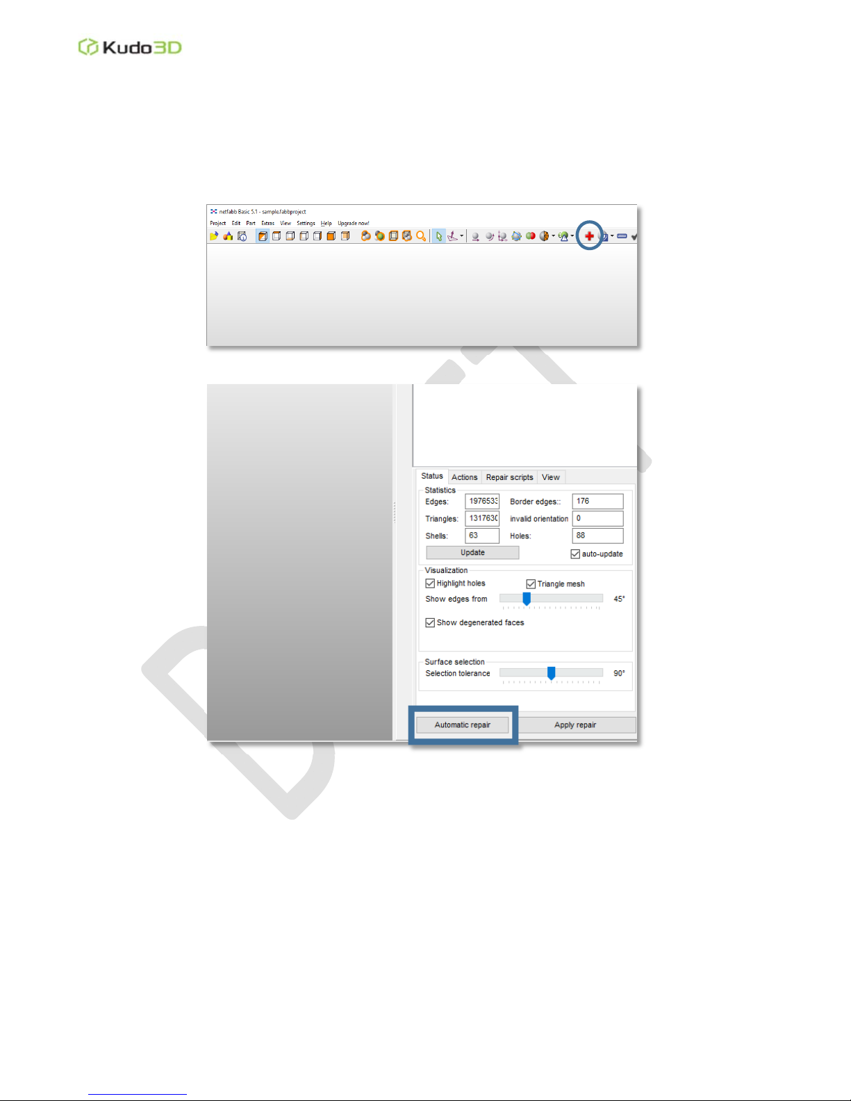
1. Error Check (Netfabb basic):
Press the “Red Cross” button on the toolbar of Netfabb basic to check for errors.
Please refer to https://www.youtube.com/watch?v=2QRvS9xdNzw for installing Netfabb basic.
2. Mesh Error Repairs:
If few errors are found, you may be able to repair the model with the “Automatic repair” of
Netfabb basic.
If Netfabb basic fails to repair, you can upload your model to Netfabb online
(https://service.netfabb.com/) to repair.
If Netfabb online also fails to repair, please try windows 3D builder.
3. Hollowing (Meshmixer): If you have multiple shells in a model, you may experience difficulty in
hollowing. In this case, you need to use Netfabb online to merge multiple shells into one shell before
hollowing. After hollowing, you must check the errors again.

Kudo3DBeanUserManual
Ver.1.0
10of14
Import solid .stl file to Meshmixer.
Press the “Edit” button on the left toolbar
and select “Hollow” in the list.
“Offset Distance” is the wall thickness.
Both “Solid Accuracy” and “Mesh Density”
determines how precisely you want to
hollow. The more precise the larger the
exported file. If the hollowing is too rough,
the wall may be too thin in certain area to
print.
You can chanage the hollowing
parameters and press “Update Hollow”.
To aoid a huge vacuum force during
printing, the model MUST have vent holes.
After pressing “Generate Holes”, you can
move the red dots to where you want the
holes to be opened. It is better to open
holes at the bottom or at a spot that is hard
to see.The hole radius must be greater
than 2mm.
Once the hollowing and hole generating
are set, press “Accept” to finalize.
Please note that hollowing may introduce
horizontal lines for printed models with
abrupt changes of shrinkage in the model
structure.
Tabla de contenidos
Otros manuales de Impresora 3D de Kudo3D


