DIYElectronics PRUSA I3 Instrucciones de montaje

PRUSA I3 ELECTRONICS
AND SOFTWARE GUIDE
June 2016 | Rev1.0 | DIYElectronics.co.za

1 | P a g e
Contents
1 Introduction ................................................................................................... 2
1. Helpful Symbols........................................................................................... 2
2 Electronics and Wiring ..................................................................................... 3
2.1 Electronics Wiring Reference Diagram.......................................................... 4
2.2 RAMPS Assembly: ..................................................................................... 5
2.2.1 Installing the RAMPS Shield..................................................................... 6
2.2.2 Connecting Heaters ................................................................................ 8
2.2.3 Connecting Thermistors .......................................................................... 9
2.2.4 Connecting the Endstops....................................................................... 10
2.2.5 Connecting the Auto-Level Sensor Endstop Module(Optional) .................... 11
2.2.6 Connecting Motors ............................................................................... 13
2.2.1 Connecting the LCD (Optional) .............................................................. 14
2.2.2 Connecting the RAMPS Fan ................................................................... 15
2.2.3 Connecting the Power Supply ................................................................ 17
2.2.4 Connect the Hot-End Fan ...................................................................... 18
2.2.1 Printer Firmware for RAMPS Marlin ......................................................... 20
3 Software Setup:............................................................................................ 21
3.1 Install Repetier-Host ............................................................................... 21
3.1.1 Configuring Repetier-Host:.................................................................... 22
3.1.2 A Note on CAD Software and Part Files: .................................................. 25
4 Printer Setup & Testing .................................................................................. 26
4.1 Understanding the Power Supply............................................................... 26
4.1.1 Check Wiring and Turn on Power Supply ................................................. 27
4.1.2 Connect the Printer to the PC ................................................................ 28
4.2 Printer Testing ........................................................................................ 29
4.2.1 Test 1 Thermistors:.............................................................................. 30
4.2.2 Test 2 Heating:.................................................................................... 31
4.2.3 Test 3 End Stops: ................................................................................ 32
4.2.4 Test 4 Motors: ..................................................................................... 34
4.2.5 Test 5 Extrusion: ................................................................................. 36
4.2.6 Test 6 Load and Extrude Filament: ......................................................... 38
5 FAQ............................................................................................................. 42
6 Troubleshooting:........................................................................................... 42

2 | P a g e
1Introduction
Welcome to part 2 of your DIYElectronics Prusa i3 kit assembly guide! In this section
we will discuss how to connect your electronics, setup your software and test your
printer. Please follow this guide carefully, especially with the electronics since they
are delicate! Never work on your electronics with the power on or the USB plugged
in and avoid shorting the electronics with anything metallic as this is the fast track
to disappointment.
1.1 Helpful Symbols
Warning! Please read the following text carefully!
Information: Useful tip, note or advice to help you along.

3 | P a g e
2Electronics and Wiring
This chapter deals with the installation and setup of your 3D printer electronics.
Warning: Be careful when assembling the electronics, they are delicate!
•Make sure you note wiring and connector orientations correctly and make
sure you have no short circuits.
•If you live in a low humidity area with large amounts of static electricity (E.G.
Johannesburg) we suggest you use an anti-static mat for this part of the
assembly.
Note: Your RAMPS board is assembled with motor drivers installed and the
correct firmware loaded. The assembled boards have been fully tested to ensure you
have a printer up and running with minimal fuss.

4 | P a g e
2.1 Electronics Wiring Reference Diagram
Figure 1 - Electronics Wiring Reference

5 | P a g e
2.2 RAMPS Assembly:
Note: After the mechanical assembly of the printer in the previous chapter, the
Arduino Mega and Power Supply should be installed on the printer frame.
6 | P a g e
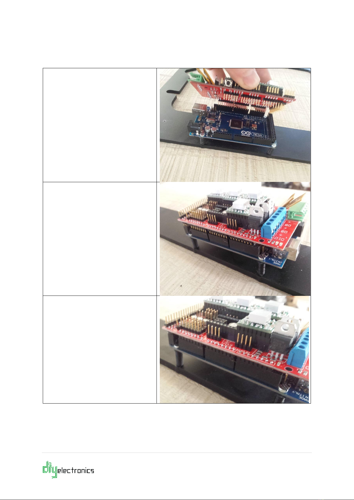
2.2.1 Installing the RAMPS Shield
Carefully connect the Ramps
board to the Arduino board. If
any of the pins are bent, gently
bend them back into place with a
screwdriver or needle nose pliers.
Line up the pins and press down.
Once you are happy that all of
the pins are in place, press down
on all edges of the Ramps board
to ensure good connections are
made.
This is what your Ramps and
Arduino assembly should look like
when pressed together properly.
Check all sides are properly
connected.

7 | P a g e

8 | P a g e
2.2.2 Connecting Heaters
Connect the heated bed wires to the D8
port and make sure they are secure.
The heated bed has no polarity; the
order of the wires does not matter.
Insert the HotEnd heater cables into
terminal D10. Tighten and ensure a
good connection.Once again the heater
has no polarity.

9 | P a g e
2.2.3 Connecting Thermistors
Place the two pin connector for
the Hotend thermistor into the
T0 position on the RAMPS board
as shown.
Do the same for the Heat Bed
thermistor into T1 position
Otros manuales para PRUSA I3
2
Tabla de contenidos
Otros manuales de Impresora 3D de DIYElectronics


