Mediant 2000
Mediant 2000 4 Document #: LTRT-70102
List of Figures
Figure 1-1: Required Steps to Install the Mediant 2000 .................................................................................... 5
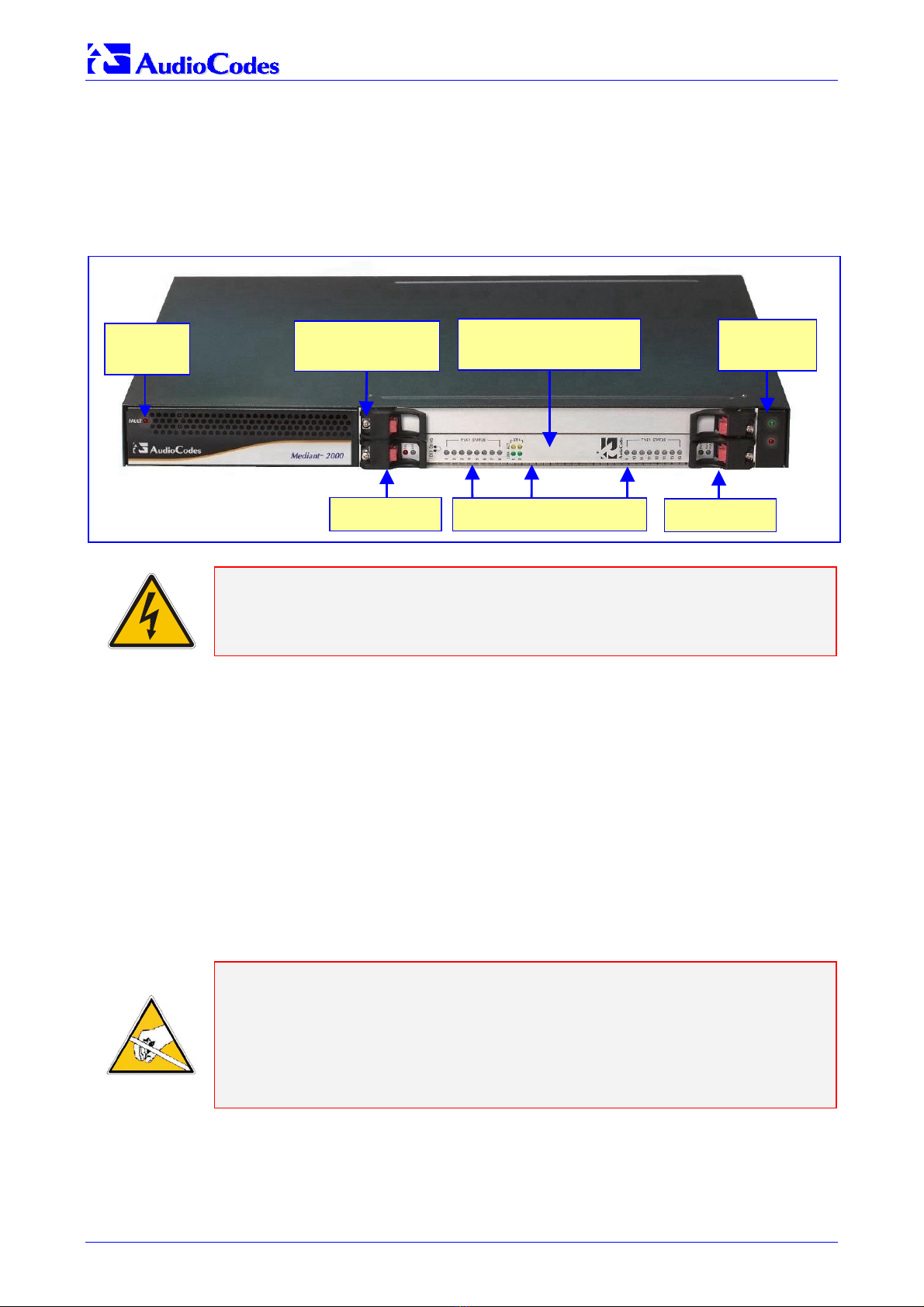
Figure 2-1: Mediant 2000 Gateway Front View ................................................................................................. 6
Figure 2-2: Plastic Bag Contents ....................................................................................................................... 7
Figure 2-3: Mediant 2000 Front View with Side Brackets.................................................................................. 8
Figure 2-4: Mediant 2000 Rear Panel Cabling (16 Trunks, AC Power)............................................................. 9
Figure 2-5: Mediant 2000 Rear Panel Cabling (8 Trunks, DC Power)) ........................................................... 10
Figure 2-6: 50-pin Female Telco Board-Mounted Connector .......................................................................... 11
Figure 2-7: Pinout of RJ-48c Trunk Connectors .............................................................................................. 11
Figure 2-8: Pinout of RJ-45 LAN Connectors .................................................................................................. 12
Figure 2-9: DC Power Connector with a Screw Connection Type Terminal Block.......................................... 13
Figure 2-10: Terminal Block with a Crimp Connection Type ........................................................................... 13
Figure 3-1: Embedded Web Server Login Screen...........................................................................................15
Figure 3-2: Mediant 2000 MGCP/MEGACO Quick Setup Screen................................................................... 16
Figure 3-3: Mediant 2000/H.323 Quick Setup ................................................................................................. 18
Figure 3-4: Mediant 2000/SIP Quick Setup ..................................................................................................... 20
Figure 3-5: Trunk Settings Screen ................................................................................................................... 22
Figure 4-1: Change Password Screen............................................................................................................. 23
Figure 5-1: Configuration File Screen .............................................................................................................. 24
Figure 6-1: Trunk & Channel Status Screen .................................................................................................... 26
Figure 6-2: Mediant 2000 Trunks Color Coding............................................................................................... 26
Figure 6-3: Specific B-channel Status Details ................................................................................................. 27
Figure 7-1: Start Software Upgrade Screen .................................................................................................... 28
Figure 7-2: Load a cmp File Screen................................................................................................................. 29
Figure 7-3: cmp File Successfully Loaded into the Device Notification ........................................................... 30
Figure 7-4: Load an ini File Screen.................................................................................................................. 31
Figure 7-5: Load a CPT File Screen ................................................................................................................ 32
Figure 7-6: FINISH Screen .............................................................................................................................. 33
Figure 7-7: ‘End Process’ Screen .................................................................................................................... 33
Figure 7-8: Auxiliary Files Screen .................................................................................................................... 35
List of Tables
Table 2-1: E1/T1 Connections on each 50-pin Telco Connector..................................................................... 11
Table 3-1: Mediant 2000 Default IP Address & Subnet Mask ......................................................................... 14
Table 6-1: Chassis LED Indicators .................................................................................................................. 25
Table 6-2: Status LED Indicators ..................................................................................................................... 25
Table 6-3: E1/T1 Trunk Status LED Indicators ................................................................................................ 25
Table 6-4: Ethernet LED Indicators.................................................................................................................. 26
Table 6-5: cPCI LED Indicators ....................................................................................................................... 26
Table 7-1: Auxiliary Files Descriptions............................................................................................................. 34