Wi-Tek WI-PCES306G Manual de usuario


This manual applies to the following switch models
model
Interface
WI-PCES306G
4-port PoE+ and 2-port RJ45
WI-PCES310GF
8-port PoE+ and 2-port SFP
Copyright notice
Disclaimers
Preface
Reader object
This document is suitable for the following people
Network Engineer
Technical Promotion Personnel
Network Administrator
Technical Support
Website:
Agreement in this book
1. Command line format Convention
The meaning of the command line format is as follows:
Bold: the command line keywords (the parts that must be input as they remain unchanged
in the command) are expressed in bold font.
Italics: command line parameters (parts of the command that must be replaced by actual
values) are expressed in italics.
[]: indicates the part enclosed by [], which is optional during command configuration.
{ x | y | ... }:Indicates that one of two or more options is selected.
[ x | y | ... ]:Indicates to select one or none of two or more options.
//: a line starting with a double slash is represented as a comment line.
2. Description
Some port types illustrated in this manual may be inconsistent with the actual
situation. In actual operation, it is necessary to configure according to the port types
supported by each product.
The display information illustrated in this manual may contain the contents of other
product series (such as product model, description, etc.), and the specific display
information shall be subject to the actual equipment information.

1 Overview ................................................................... 4
2 Configuration Guide ..........................................................4
2.1 Power ................................................................ 4
2.2 Connecting to the Network ............................................... 5
2.3 Starting the Web-based Configuration Utility ................................5
2.5 Logging In ............................................................ 6
2.6Web-based Switch Configuration ...........................................7
3 Web Smart Configuration ..................................................... 9
3.1 Homepage ............................................................. 9
3.2 System Settings ........................................................ 9
3.2.1 Device Info ...................................................... 9
3.2.2 IP Settings ...................................................... 9
3.2.3 WEB Settings ................................................... 10
3.2.4 Telnet Settings .................................................. 10
3.2.5 User Management ...............................................11
3.2.6 Upgrade ....................................................... 11
3.2.7 Device Management ............................................. 11
3.3 Monitoring ............................................................12
3.3.1 Port Statistics ................................................... 12
3.3.2 Cable Diagnostics ............................................... 12
3.3.3 Loop Guard .....................................................13
3.4 Switch Settings ....................................................... 13
3.4.1 Port Settings ....................................................13
3.4.2 Port Mirroring ................................................... 14
3.4.3 Port Isolation ................................................... 15
3.4.4 Static MAC ..................................................... 15
3.4.5 Filter MAC ......................................................16
3.4.6 Search MAC .................................................... 16
3.4.7 MAC List ....................................................... 16
3.4.8 DHCP Snooping ................................................ 17
3.5 VLAN Settings ........................................................ 18
3.5.1 VLAN Member .................................................. 18
3.5.2 VLAN Settings .................................................. 18
3.6 QoS Settings ......................................................... 19
3.6.1 Port Rate .......................................................19
3.6.2 Storm Control ................................................... 20
3.7 PoE Settings .......................................................... 21
3.7.1 PoE Global Info ................................................. 21
3.7.2 PoE Basic settings .............................................. 22
3.8 Onvif ................................................................ 22
3.9 Cloud Settings ........................................................ 23
4 Frequently Asked Questions ................................................. 24

Web Smart Function Configuration
1 Overview
Web Smart refers to the device web management system, that is, the web management
system that manages or configures the device, and manages the device by accessing
Web Smart using a browser (such as Chrome).
Web management includes two parts: Web server and Web client. The Web server is
integrated on the device to receive and process the requests sent by the client and return
the processing results to the client. The Web client usually refers to the browser, such as
Chrome, IE and FF.
2 Configuration Guide
This section provides an introduction to the web-based configuration utility, and covers the
following topics:
• Powering on the device
• Connecting to the network
• Starting the web-based configuration utility
2.1 Power
Connecting to Power
Power down and disconnect the power cord before servicing or wiring a switch.
Do not disconnect modules or cabling unless the power is first switched off. The
device only supports the voltage outlined in the type plate. Do not use any other
power components except those specifically designated for the switch.
Disconnect the power cord before installation or cable wiring.
Connect the AC power connector on the back panel of the switch to the external power

source with the included power cord, and check the power LED is on.
2.2 Connecting to the Network
To connect the switch to the network:
1. Connect an Ethernet cable to the Ethernet port of a computer
2. Connect the other end of the Ethernet cable to one of the numbered Ethernet ports of
the switch. The LED of the port lights if the device connected is active.
3. Repeat Step 1 and Step 2 for each device to connect to the switch.
We strongly recommend using CAT-5E or better cable to connect network
devices. When connecting network devices, do not exceed the maximum cabling
distance of 100 meters (328 feet). It can take up to one minute for attached
devices or the LAN to be operational after it is connected. This is normal
behavior.
Connect the switch to end nodes using a standard Cat 5/5e Ethernet cable (UTP/STP) to
connect the switch to end nodes as shown in the illustration below.
Switch ports will automatically adjust to the characteristics (MDI/MDI-X, speed, duplex) of
the device to which the switch is connected.
2.3 Starting the Web-based Configuration Utility
This section describes how to navigate the web-based switch configuration utility. Be sure
to disable any pop-up blocker.
Launching the Configuration Utility
To open the web-based configuration utility:
1. Open a Web browser.
2. Enter the IP address of the device you are configuring in the address bar on the
browser (factory default IP address is 192.168.0.1) and then press Enter.
After a successful connection, the login window displays.

2.5 Logging In
The default username is admin and the default password is admin.
To log in to the device configuration utility:
1. Enter the default user ID (admin) and the default password (admin).
2. If this is the first time that you logged on with the default user ID (admin) and the
default password (admin) it is recommended that you change your password immediately.
When the login attempt is successful, the System Information window displays.
If you entered an incorrect username or password, an error message appears and the
Login page remains displayed on the window.
By default, the application logs out after five minutes of inactivity.
To logout, click Logout in the top right corner of any page. The system logs out of the
device.
When a timeout occurs or you intentionally log out of the system, a message appears and

the Login page appears, with a message indicating the logged-out state. After you log in,
the application returns to the initial page.
2.6Web-based Switch Configuration
The Websmart switch software provides Layer 2 functionality for switches in your
networks. This chapter describes how to use the web-based management interface (Web
UI) to configure the switch’s features.
For the purposes of this manual, the user interface is separated into three sections, as
shown in the following figure:
As you can see, the page is divided into two parts:
The left part is the menu bar, which displays the links of all configuration functions of the
equipment, such as monitoring management and switch configuration module.
The right part is the content area, which is divided into upper and lower parts. The upper
side is the port status bar, Chinese and English display switching and 《Logout》button,
and the lower side is the page content presentation and configuration area.
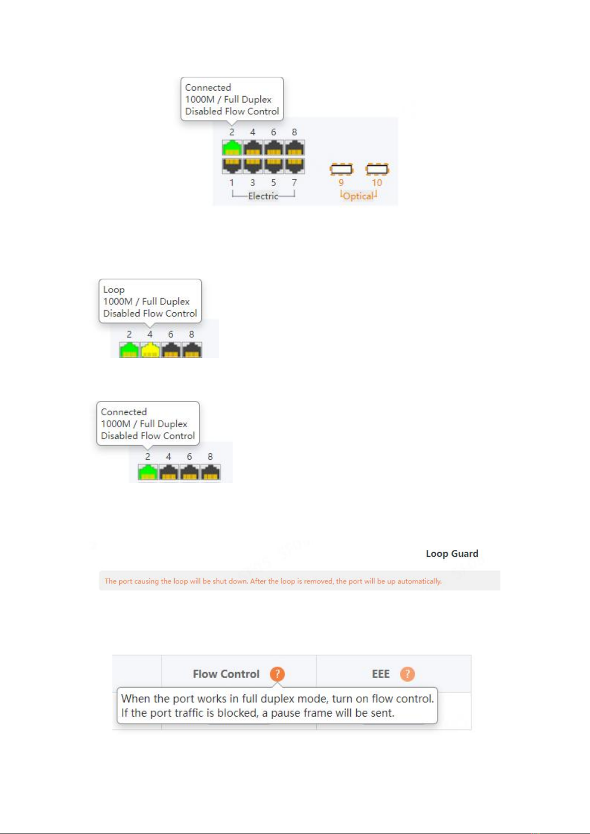
Port Status Bar:
Move the mouse to the port to display the basic status of the port (including port
connection status, rate duplex and flow control status).

When a loop appears on the port, the port icon displays yellow
When the port works normally, the port icon displays green
The content area sometimes presents orange text (indicating the description of the
function block)
And a question mark with an orange background (indicating the prompt description of the
operation, and the mouse moves up to display the description text).

3 Web Smart Configuration
3.1 Homepage
The homepage interface displays the basic information of the device.
3.2 System Settings
3.2.1 Device Info
Configure the information of the device, including Device Name, Device Contact and
Device Location.
3.2.2 IP Settings
Configure device management IP (default static IP: 192.168.0.1)

Tips:
1. When configuring IP, the device will be disconnected briefly. If automatic IP acquisition
is enabled, you need to obtain the configuration IP from the uplink device or web
management through device management IP: 10.XX.XX.XX(XX.XX.XX is the last three
digits of the MAC address of the current device).
3.2.3 WEB Settings
Configure web page timeout, default is 10 minutes.
Tips:
1. The timeout can be configured for 1-60 minutes
3.2.4 Telnet Settings
Configure Telnet timeout, default is 10 minutes.
Tips:
1. The timeout can be configured for 1-60 minutes
Este manual sirve para los siguientes modelos
1
Tabla de contenidos
Otros manuales de Cambiar de Wi-Tek

Wi-Tek
Wi-Tek WI-PMS310GF-Alien Manual de usuario

Wi-Tek
Wi-Tek FTTH ONU EQUIPMENT Manual de usuario

Wi-Tek
Wi-Tek WI-PCMS310GF Manual de usuario

Wi-Tek
Wi-Tek WI-PMS310GF-Alien-I Manual de usuario

Wi-Tek
Wi-Tek WI-PS306GF-I Manual de usuario

Wi-Tek
Wi-Tek WI-PS518GF Manual de usuario

Wi-Tek
Wi-Tek WI-PMS310GF-UPS Manual de usuario