VOLKTEK INS-802 Manual de usuario

8-port 10/100Base-TX
+2-port 100Base-FX
Switch
(INS-802 / INS-802W)
User Manual

COPYRIGHT
All rights reserved. No part of this publication may be reproduced,
stored in a retrieval system, or transmitted in any form or by any means,
whether electronic, mechanical, photo copying, recording or otherwise,
without the prior written permission of the publisher.
FCC WARNING
This equipment has been tested and found to comply with the
limits for a class A device, pursuant to part 15 of FCC rules.
These limits are designed to provide reasonable protection against
harmful interference in a commercial installation. This equipment
generates, uses and can radiate radio frequency energy and, if not
installed and used in accordance with the instructions, may cause
harmful interference to radio communication. Operating this equipment
in a residential area is likely to cause harmful interference, in which
case the user will be required to correct the interference at the user’s
own expense.
CE
This is a Class A product. In a domestic environment, this
product may cause radio interference in which case the user
may be required to take adequate measures.
Take special care to read and understand all content given in the
warning boxes
Warning

TA BL E O F CONTEN TS
ABOUT THIS GUIDE............................................................ 4
TERMS/USAGE ....................................................................... 4
INTRODUCTION ................................................................... 4
INDUSTRIAL ETHERNET TECHNOLOGY .................................. 5
SWITCHING TECHNOLOGY ..................................................... 5
FEATURES .............................................................................. 6
INS-802 INDUSTRIAL SWITCH – UNPACKING AND
SET-UP ................................................................................... 7
UNPACKING ........................................................................... 7
LAYOUT OF THE INS-802/802W............................................ 8
DIN RAIL MOUNTING OF THE INS-802/802W..................... 10
REDUNDANT POWER INPUTS................................................ 11
CONFIGURING DC POWER INPUTS........................................ 11
ETHERNET CONNECTIONS.................................................... 13
LED INDICATORS ................................................................ 14
EXTERNAL ALARM CONTACT .............................................. 15
DIP SWITCH SETTINGS ........................................................ 16
FIBER CONNECTOR .............................................................. 17
AUTO-NEGOTIATION ............................................................ 17
SWITCHING,FILTERING,AND FORWARDING ........................ 18
PORT SPEED &DUPLEX MODE ............................................ 18
TECHNICAL SPECIFICATIONS ...................................... 19
APPENDIX ........................................................................... 21

4
ABO U T THI S GU I D E
The INS-802/INS-802W Industrial Series Switch is a hardened,
8-port Ethernet Switch with dual fiber uplinks and redundant DC
power inputs – to provide a reliable and economical solution for
your industrial Ethernet environment. With its dry contact smart
alarm, the INS-802/802W can initiate a physical alarm (audible
and/or visible) in the event of a malfunction. The Switch
operates in a wide temperature range, from -10°C to 70°C
(from -40°C in the case of the 802W), and is designed to handle
higher than normal degrees of vibration and shock, making it
suitable for harsh industrial environments.
This manual discusses how to install the INS-802/INS-802W
Industrial Fast Ethernet Switch.
The INS-802Wis able to operate in a wider temperature range
(from -40°C to 70°C). The rest of the features and functions are
the same as the INS-802.
Terms/Usage
In this guide, the term “Switch” (first letter uppercase) refers to
the INS-802/802W Industrial Fast Ethernet Switch, and ”switch”
(first letter lowercase) refers to all other Ethernet switches.
In this guide, the term INS-802 will also refer to the INS-802W.
INT R O D U C TI O N
This chapter describes the features of the Switch and some
background information about Ethernet/Fast Ethernet switching
technology.

5
Industrial Ethernet Technology
The growing importance of Ethernet has extended to the factory
floor and industrial environments, where things have become
too harsh for typical commercial-grade networking equipment.
VOLKTEK has created an Industrial Series of Switches and
interconnecting devices specifically for the purpose of extending
Ethernet to the factory floor and industrial environments. All of
our Industrial Series devices are delivered in a rugged,
hardened case and with components capable of withstanding a
high degree of vibration and shock. These devices also operate
well in temperatures as high as 70°C.
Not an ordinary office switch by any means, the INS-802 is
engineered and designed specifically for the harsh, industrial-
type environments commonly encountered in heavy industry.
With its redundant DC power inputs and high-performance
components, the INS-802 is perfectly suited for the industrial
Ethernet.
Switching Technology
One way to push the limits of Ethernet technology, is the
development of switching technology. A switch bridges Ethernet
packets at the MAC address level of the Ethernet protocol that
are transmitted between connected Ethernet or Fast Ethernet
LAN segments.
Switching is a cost-effective way of increasing the total network
capacity available to users on a local area network. A switch
increases capacity and decreases network loading by dividing a
local area network into different segments which don’t compete
with each other for network transmission capacity.

6
Features
The Switch was designed for easy installation and high
performance in an industrial environment where vibration, shock,
heat, and RF interference may be commonplace.
The Switch was specifically designed to be small and compact
for easy DIN-rail mounting and it can be installed where space
is limited.
The Switch is ideal for deployment with multiple high-speed
servers for shared-bandwidth 10Mbps or 100Mbps workgroups.
With a maximum bandwidth of 200Mbps (100Mbps full-duplex
mode), any port can provide workstations with a congestion-free
data pipe for simultaneous access to the server.
The Switch can be expanded by cascading two or more
switches together in a ‘daisy chain’. As all ports support
200Mbps (half-duplex), the Switch can be cascaded from any
port and to any number of switches.
The Switch combines dynamic memory allocation with store-
and-forward switching to ensure that the buffer is effectively
allocated for each port, while controlling the data flow between
the transmit and receive nodes to guarantee against all possible
packet loss.
The Switch is an unmanaged 10/100Mbps Fast Ethernet Switch
that offers solutions for increasing the bandwidth and speed of
small Ethernet workgroups.
Other features are:
oEight (8) 10/100Base-TX and Two (2) 100Base-FX (SFP-
type fiber transceivers)
oRugged, hardened IP30 Case
oVibration/Shock operational

7
oPower terminal block
oWide voltage range: 9-48V
oDIP Switch to enable or disable alarm functions
oPower-input polarity protection function
oUnder-power and over-power detection function
oWide operating temp.: -10°C - 70°C / -40°C - 70°C (802W)
oStore-and-forwarding
oAuto-negotiation at all copper ports
INS-802 IN D U S T R IA L SW I T C H –
UN PA CK I NG AN D SET-U P
This section and the following sections explain the set-up
and installation of the VOLKTEK INS-802/802W
Industrial Switch.
Unpacking
Open the box of the Switch and carefully unpack it. The
box should contain the following items:
One INS-802 8-port 10/100TX plus dual fiber uplink
Industrial Fast Ethernet Switch
One DIN-rail bracket
Protective caps for unused ports
Quick Installation Guide
This User’s Guide CD
If any item is found missing or damaged, please contact
your local reseller for replacement.

8
Layout of the INS-802/802W
Front View of Switch
1. Fiber Port Offline LED x 2
2. Fiber Port LNK/ ACT x 2
3. Fiber 100Mbps LED x 2
4. Primary Power LED
5. Redundant Power LED
6. Alarm LED
7. 2 x 100Base-FX LC Fiber
slots (SFP-type)
8. 10/100Base-TX ports (8)
9. TX Port 100Mbs LED
10. TX Port LNK/ ACT LED
1
2
3
5
4
6
7
8
9
10
9
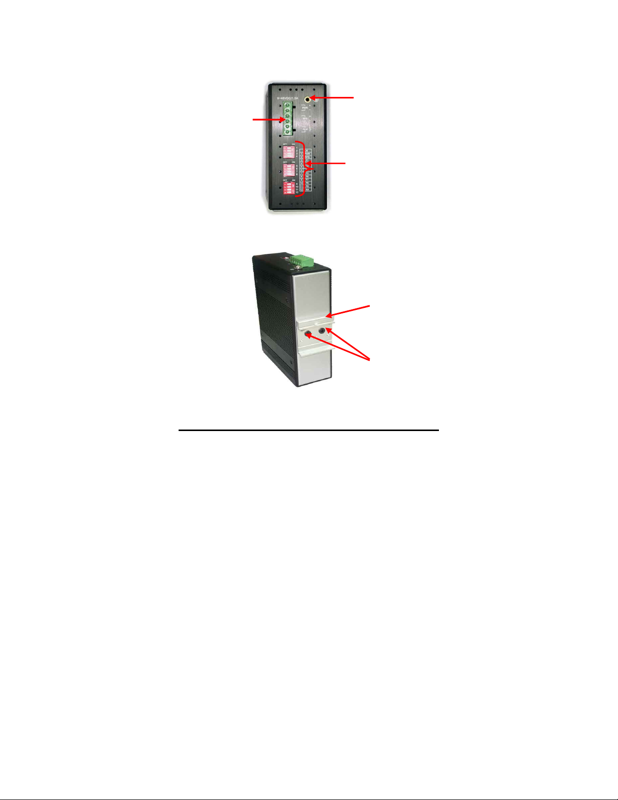
TOP View of Switch
Back View of Switch
Din Rail
Bracket
Screws
Grounding
Screw
Terminal block for
power input
(PWR/RPS), and alarm
dry contact
DIP Switches

10
DIN Rail Mounting of the INS-802/802W
The aluminum DIN-rail attachment plate should already
be affixed to the back panel of the Switch. If you need to
attach the DIN-rail plate, assure that the stiff metal spring
is situated towards the top. Attaching the Switch to the
DIN-rail is easy: just align and hook it over the top rail,
making sure that the metal spring (thin bent rod) is in
front of the rail edge as the rail edge bites into the space
behind this spring, then press down and press the
Switch forward to snap into the bottom rail, as shown in
the figures below.
The set-up of the Switch can be performed after checking
the following facts:
•The hanging structure must support at least 1.0 Kg
for the Switch.
•The power outlet should be within 1.82 meters (6 feet)
Este manual sirve para los siguientes modelos
1
Tabla de contenidos
Otros manuales de Cambiar de VOLKTEK

VOLKTEK
VOLKTEK NSH-9308P Manual de usuario

VOLKTEK
VOLKTEK INS-801W Manual de usuario

VOLKTEK
VOLKTEK NSH-5632 Manual de usuario

VOLKTEK
VOLKTEK INS-806 Manual de usuario

VOLKTEK
VOLKTEK NSH-5509 Manual de usuario

VOLKTEK
VOLKTEK IEN-8428P-24V Manual de usuario

VOLKTEK
VOLKTEK HNS-8415P Manual de usuario

VOLKTEK
VOLKTEK NSH-2926 Manual de usuario

VOLKTEK
VOLKTEK NSH-9309 Manual de usuario

VOLKTEK
VOLKTEK INS-8424P Manual de usuario


