US Cutter LaserPoint 2 Manual de usuario

Cutting Plotter
Operation Manual

Thanks very much for purchasing cutting plotter.
For ensuring you to make best use of your machine, please reading this
manual carefully and thoroughly before starting to use it.
Please turn off the power quickly if you encounter any problems, and
refer to this manual or contact your dealer.
Special Declaration
1. Manufacturer keeps the right of changing
product specification without prior notice;
2. Manufacturer only takes the legal duty of
product itself, not undertaking any other loss
produced after product was wrong;

Contents
Chap1.Attention -------------------------------------------------------- (1)
Chap2. Packing-box Contents and Installation --------------------- (2)
Chap3. Items of components ------------------------------------------ (4)
Chap4. Firstly testing when energized ------------------------------- (5)
Chap5. Controlling panel operation ---------------------------------- (6)
Chap6. Cutter and plotter ---------------------------------------------- (8)
Chap7. Loading paper -------------------------------------------------- (9)
Chap8. Lift up / adhere ------------------------------------------------ (10)
Chap9.After work over ----------------------------------------------- (11)
Chap10. Using life of the cutter ------------------------------------- (11)
Chap11. Parameters Table -------------------------------------------- (12)
Chap12. Questions and answers ------------------------------------- (13)
Chap13. Phenomena not wrong ------------------------------------- (14)

Operation Manual
-1-
Chap 1 Attention
Ensure the supply voltage varying within the range of ±10%, otherwise a
voltage stabilizer must be used.
Please don’t place any small iron-magnetic subject near the carriage.
Prevent from dropping foreign matters into cracks such as pins, little screws,
etc.
Please pull down the power plug if not using during a long time.
Don’t pull the cable with power when it is connected to the computer.
Don’t press the pinch roller on the grit roller, if it is not used.
Always connect the power cord to a grounded outlet.
Don’t push the carriage.
Don’t contact the carriage or the roller when the machine is working.
.

Operation Manual
-2-
Chap 2 Packing-box Contents and Installation
2-1 Packing-box
Please carefully check up the goods after opening the packing box, and in
every box there should be as following:
1. A main machine.
2. A packet of accessories.
3. A set of parts of machine stand.
2-2 Accessories
NO.
Item
Quantity
1
Power cord
1
2
Operation manual
1
3
Cutter holder
1
4
Cutter
3
5
Plotter holder
1
6
Refill
1
7
Serial communication cable
1
8
Parallel communication cable
1
9
Cover
1
2-3 Parts of stand
NO.
Item
Quantity
1
Left column
1
2
Right column
1
3
Crossbeam
1
4
Pillar-bars
2
5
Pillars
4
6
Paper roller
1
7
Paper hanger
2
8
Connection board
2
9
Screw M4
×
20
12
10
Screw M4
×
8
8

Operation Manual
-3-
2-4 Assembly of machine stand
Referring to the following drawing:
Step 1: Rotate the stand pillars into screw thread-holes in the pillar bars, and then
connect the pillar bars to left and right columns with screws respectively.
Step 2: Connect the crossbeam to left and right columns with screws.
Step 3: Join the paper hanger to the inside of the left and right columns with screws.
Step 4: Join the connection board to the top of the left and right columns with
screws.
Step 5: Lay down the four pillars of main machine, place the machine on the
connection board, and then insert the pillars into the connection board to connect to
the main machine.
Step 6: Place the paper-roller on the roller of paper hanger.

Operation Manual
-4-
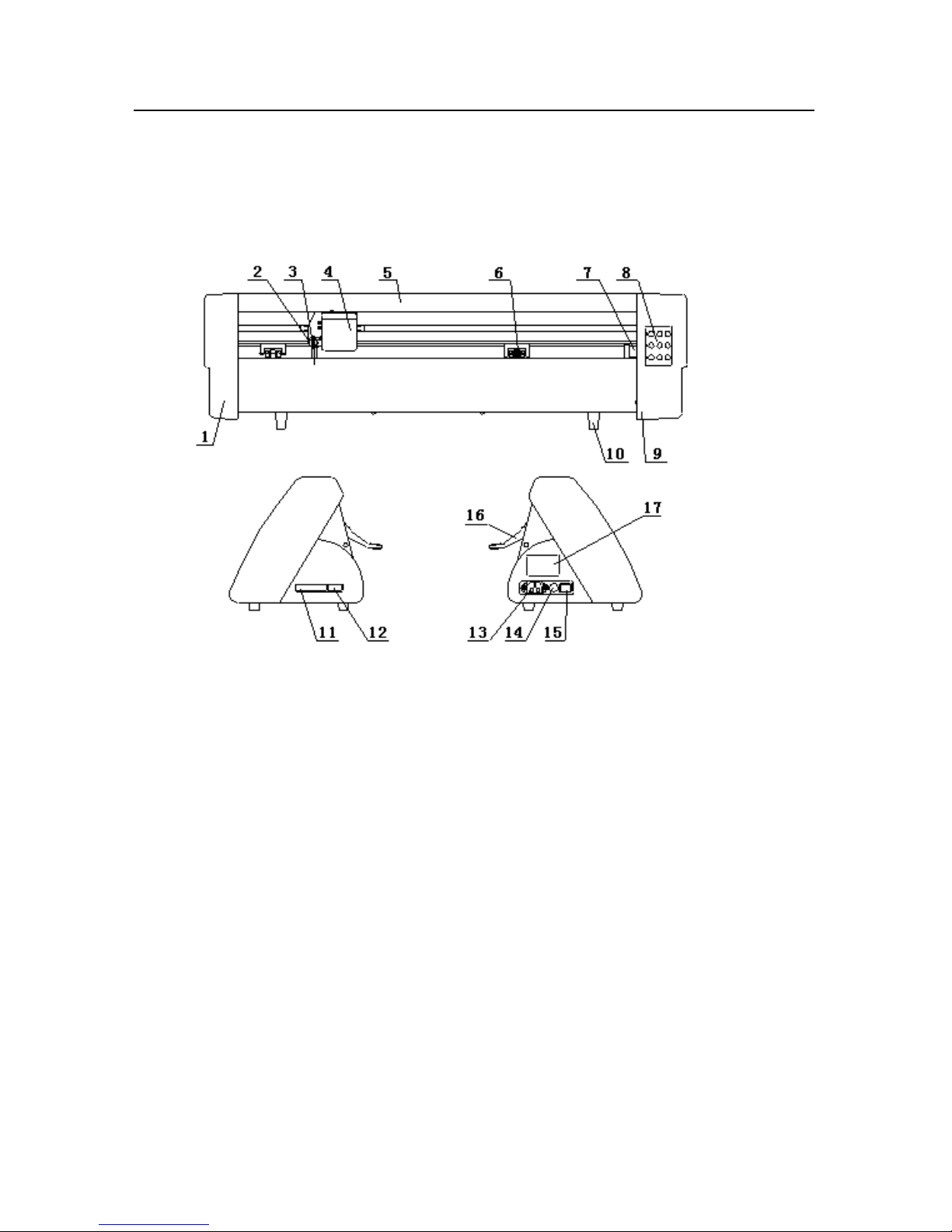
Chap 3 Items of components
3-1. _0 Types
1. Left cover
2. Cutter bracket
3. Cutter holder
4. Carriage of cutter-bracket
5. Cover of guide
6. Pinch roller
7. Pressure setting knob
8. Controlling panel
9. Right cover
10. Pillar
11. Socket of parallel port
12. Socket of serial port
13. Power socket
14. Fuse socket
15. Power switch
16. Pinch roller handle

Operation Manual
-5-
3-2. _1 Types
1. Left cover
2. Cutter bracket
3. Cutter holder
4. Carriage of cutter-bracket
5. Cover of guide
6. Pinch roller
7. Controlling panel
8. Right cover
9. Pillar
10. Socket of serial port
11. Socket of parallel port
12. Power socket
13. Fuse socket
14. Power switch
15. Pinch roller handle

Operation Manual
-6-
Chap 4 Firstly testing when energized
4-1 Installation
Place the machine on a horizontal table, adjust the height of the machine pillars
to make it stable. Do keep enough room in front and behind of the machine. And
prevent from laying it in a place of quack, strong electromagnetic disturbance or
thick dirt-powder.
To ensure the machine work safely and reliably, please connect to the ground
effectively.
Plug the power cord in the power socket of the machine and a 220V/110V AC
power outlet, and turn on the switch, and the red light lights up. Now the carriage
can move to the right side and the roller rotates automatically, thus complete the
automatic reset. If it fails to reset, press the “RESET” key please.
At the same time of turning on the switch, cutter bracket will be raised about 1.5
to 2 mm. And pressing any direction key will make it fall down.
If all goes on as the above, that proves the machine operation properly.
4-2 Remote
The machine can be communicated with computer by serial port (COM1, 2, 3, 4)
or parallel port, but can’t use them at the same time.
Using parallel port can reduce communication time and improve the efficiency
of computer.
Remote steps:
A. Turn off the computer and the machine.
B. Connect the communication cable between the according interface of the
machine and of the computer.
C. Turn on the computer and the machine, and wait for the machine
correctly resetting.
D. Start cutting software or another after confirming the software setting
(interfaces, bode-rate and commands sets) matched to the machine.
Output graphical data to the machine, and it will begin to cut.

Operation Manual
-7-
Chap 5 Controlling-panel operations
5-1. _0 Types
5-1-1 Introduction
1.State lights:
Red light: directive of power, when it is on means to be properly running.
Yellow light: directive of local, the machine is in local state when it is on and
remote state when it is off.
Green light: directive of set-up, when it is on means to be in set-up state and the
bode-rate of serial communication can be set. If the yellow and green lights flash up
at the same time, that means to be in copy state.
2.Speed lights:
Red light: directive of high speed, “on” means to be at the speed of four high
grades and “off” means at four low speed grades.
Green light: directive of speed grade, the speed grade at current is the number of
green light’s position if the red light is off, or to be added four. For example, when
the no. 3 green light and the red light are on at the same time, the grade is 7 (3 + 4 =
7).
3.Direction keys:
In local state, the carriage and the roller can be moved by pressing direction keys;
In remote state, pressing them can control the plotter up and down; In set-up state,
Este manual sirve para los siguientes modelos
1
Tabla de contenidos
Otros manuales de Trazador de US Cutter