TTI PROFESSIONALS TTICM600V Manual de usuario

400A AC/DC CLAMP METER
AUTO RANGING
PART NO:
TTICM600V
(..151478)
OPERATING
INSTRUCTIONS

2600V CLAMP METER
CONTENTS
INTRODUCTION .........................................................................................................3
• Intended Use......................................................................................................................3
• Product Contents .............................................................................................................3
GENERAL SAFETY ......................................................................................................4
SAFETY INSTRUCTIONS............................................................................................4
• Electrical Symbols.............................................................................................................5
GENERAL SPECIFICATIONS......................................................................................6
EXTERNAL OVERVIEW ..............................................................................................6
• Function Selector Overview............................................................................................7
• LCD Screen Overview .......................................................................................................8
• Buttons Overview .............................................................................................................8
OPERATING INSTRUCTIONS....................................................................................9
• AC/DC Current Measurement .........................................................................................9
• AC/DC Voltage and Voltage Frequency (% Duty Cycle) Measurement...................10
• Continuity Test / Resistance / Diode / Capacitance Measurement .........................11
• Non-Contact (NCV) AC Electric Field Sensing .............................................................12
• Other Functions.................................................................................................................13
TECHNICAL INDEX.....................................................................................................14
• Accuracy Specications ...................................................................................................14
• DC Current Measurement................................................................................................14
• AC Current Measurement................................................................................................14
• DC Voltage Measurement................................................................................................14
• AC Voltage/Voltage Frequency ......................................................................................15
• Resistance Measurement ................................................................................................15
• Continuity/Diode Measurement....................................................................................16
• Capacitance Measurement .............................................................................................16
• Duty Ratio Measurement ................................................................................................16
• Frequency Measurement.................................................................................................17
• Non-Contact AC Voltage Detecting (NCV) ...................................................................17
MAINTENANCE...........................................................................................................18
• General Maintenance.......................................................................................................18
• Battery Replacement........................................................................................................18
WARRANTY INFORMATION .....................................................................................20

3OPERATING MANUAL
INTRODUCTION
TTICM600V is a true RMS (4000 count) auto ranging digital clamp meter.
This meter measures AC/DC Current, AC/DC Voltage, Resistance, Capacitance, Diode Test,
Continuity and Non Contact Voltage detection.
The instruction manual includes relevant safety information and warning indication, please
read them carefully and strictly observes all warnings and notes.
INTENDED USE
The clamp meter is to be used only for electrical inspection within the specications the
machine is rated for. Failure to use the machine within the specications may result in serious
injury or death.
PRODUCT CONTENTS
CAUTION
!The supplied test leads are used for MAINS measurements CATll 1000V,
CATlll 600V according to IEC 61010-031
Unpack and take out the clamp meter, please check carefully if the following attachments are
complete or intact.
1. Operating instruction manual
2. Pair Test Leads
3. TTTICM600V Clamp Meter

4600V CLAMP METER
GENERAL SAFETY
Prior to using clamp meter, please read the product manual and ensure you have a solid
understanding of the meter’s functions and features.
CAUTION
!Upon rst use of the machine, ensure the test leads aren’t damaged and
in good working order.
WARNING
!
The warnings, cautions, and instructions discussed in this instruction
manual cannot cover all possible conditions or situations that could
occur. It must be understood by the operator that common sense and
caution are factors that cannot be built into this product, this must be
supplied by the operator.
SAFETY INSTRUCTIONS
Please note the “warning signs and words”. Warning means the condition or action that may
cause threat to user or damage to the instrument or equipment to be measured.
The clamp meter is designed according to EN61010-1, 61010-2 and electromagnetic radiation
protection EN61326-1 safety standards, CATII 600V, CATIII 300V and pollution grade II.
If the meter is not used properly as per the instructions, the protection provided may be
weakened or lost.
Anyone using this instrument should be knowledgeable and trained about the risks involved
with measuring voltage, especially in an industrial setting, and the importance of taking safety
precautions and of testing the instrument before and after using it to ensure that it is in good
working condition.
This product has been tested to the requirements of IEC 61010
CAT II: Applicable to test and measuring circuits connected directly to utilization points
(socket outlets and similar points) of the low-voltage MAINS installation.
CAT Ill: Applicable to test and measuring circuits connected to the distribution part of the
building’s low-voltage MAINS installation.
•Check the clamp meter and test leads before using, guard against any damage.
If any abnormalities or damage are found, do not use the clamp meter.
•Examine the test leads for damaged insulation or exposed metal.
Check test lead continuity. Replace damaged test leads before using the Meter.
•Do not use the clamp meter without having rear cap and battery cover in place, otherwise
electric shock may occur.
•To avoid false readings that can lead to electrical shock and injury, replace the batteries as
soon as the low battery indicator appears.
•When using the test leads, keep ngers behind the nger guards on the probes.
Do not contact the bare wire and connector, unused input terminal or the circuit being
measured when clamp meter is in operation.
•Connect the common test lead before connecting the live test lead.
When disconnecting test leads, disconnect the live test lead rst.
•Function selector shall be set at the correct position prior to measurement.
Do not change selector settings while measuring to guard against damage to the meter.

5OPERATING MANUAL
•Refrain from applying voltage over DC1000V/AC750V between the clamp meter terminals
and ground to guard against electric shock and clamp meter damage.
•Be careful in measuring RMS voltage higher than DC or AC 30V, such voltage poses a shock
hazard.
•Do not measure current in circuits carrying more than 600A with the meter jaw.
•Do not measure voltage or current higher than the allowable input value.
•Disconnect circuit power and discharge all high-voltage capacitors before you measure
resistance, continuity, or capacitance.
•Do not modify the internal wiring in the meter to guard against damage to the meter and
danger.
•Do not store or use clamp meter in an explosive or ammable environment, high
temperature, high humidity or strong electromagnetic eld.
•Comply with local and national safety regulations and requirements. Use personal
protective equipment such as approved rubber gloves, face protection, and ame-
resistant clothing to prevent shock and arc blast injury where hazardous live conductors
are exposed.
•Clean the clamp meter case with soft cloth and neutral detergent. To prevent causing
corrosion to the case, or damage to the instrument do not use abrasives or solvents.
Make sure all water is removed before use.
ELECTRICAL SYMBOLS
Double insulation Diode measurement
Grounding AC or DC (alternating current or direct current)
Warning High voltage hazard
AC (alternating current) Continuity measurement
DC (direct current) This symbol signies product complies with
Australian requirements
Capacitance

6600V CLAMP METER
GENERAL SPECIFICATIONS
•Display count: 4000
•Polarity display: Auto
•Maximum jaw opening: 28 mm
•Power supply: 2 x AAA 1.5V batteries
•Dimension: 215mm x 63mm x3mm
EXTERNAL OVERVIEW
1.
2.
4.
6.
3.
7.
10.
9.
5.
8.
1. NCV sensor
2. Clamp jaws
3. Hand guard
4. LED indicator
5. Jaw opening trigger
6. Function selector
7. LCD display
8. Function buttons
9. Terminal input jack (red and positive +)
10. COM input jack (black and negative -)

7OPERATING MANUAL
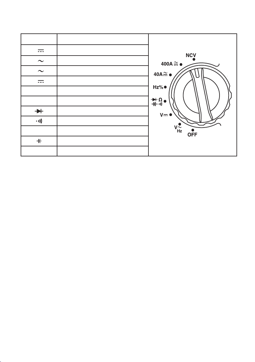
FUNCTION SELECTOR OVERVIEW
POSITION DESCRIPTION
VDC voltage measurement
VAC voltage measurement
AAC current measurement
ADC current measurement
NCV Non-contact voltage measurement
Hz% Frequency/ duty radio measurement
Diode measurement
Continuity measurement
ΩResistance measurement
Capacitance measurement
OFF Shut-down

8600V CLAMP METER
LCD SCREEN OVERVIEW
SYMBOL DESCRIPTION
Caution AC/DC voltage is higher
than 30V
Data hold
Negative reading
AC/DC AC/DC measurement
Low battery indicator
Diode measurement
Continuity measurement
Relative value measurement
Ω, k Ω, M Ω Resistance unit
mV, V Voltage unit
μA, mA, A Current unit
nF, μF, mF Capacitance unit
Hz% Frequency unit, duty radio
βTransistor amplication factor
NCV Non-contact voltage measurement
LED LED measurement
Auto power o
BUTTONS OVERVIEW
BUTTON DESCRIPTION
SELECT
In composite scale, press this button to switch between the corresponding functions
or ranges.
REL/ZERO
Press this button to store the current reading as a reference for future readings. When
the LCD display value is reset to zero, the stores reading will be subtracted from the
future readings. Press this button again to exit the relative value mode.
MAX/MIN
Short press of this button will enter the maximum/minimum measurement mode and
long press will exit the function. *Valid for ACV/DCV, ACA/DCA,°C/°F, resistance and
capacitance scales*
HOLD/
A short press of this button will enter or exit the data hold mode; a long press
(about 2s) will turn the LCD backlight on or o
DC
AC
AUTO MAXMIN ZERO
MkΩ Hz%nmFVA˚C˚F
NCV
H

9OPERATING MANUAL
OPERATING INSTRUCTIONS
AC/DC CURRENT MEASUREMENT
1. Select the corresponding current range.
2. Press the trigger to open the clamp jaws, and fully enclose one conductor.
3. Only one conductor can be measured at a time, or the measurement reading will
be wrong.
NOTE:
•Do not insert the testing leads during current measurement to avoid electric shock.
•The current measurement must be taken with safeguard protection.
•Press the REL button to return to zero before the DC current measurement, and
meanwhile the centre hole of the jaw should be perpendicular to the current direction to
ensure accuracy.
•The open circuit zeroing reading may be relatively large after (high) DC current
measurement. Please perform the AC current detection again to counteract the
remanence signal by alternating electric eld.
SELECT
SELECT
REL/ZERO
MAX/MIN HOLD/
True RMS
AC/DC CLAMP METER
AC/DC CLAMP METER
NCV
400A
40A
V
V
Hz%
Hz
OFF
Ω
V
Hz
COM
CAT III 300V
CAT III 600V
Ω
REL/ZERO
MAX/MIN HOLD/
True RMS
NCV
400A
40A
V
V
Hz%
Hz
OFF
Ω
V
Hz
COM
CAT III 300V
CAT III 600V
Ω
AUTO
Hz
AUTO
Hz

10 600V CLAMP METER
AC/DC VOLTAGE AND VOLTAGE FREQUENCY (% DUTY CYCLE)
MEASUREMENT
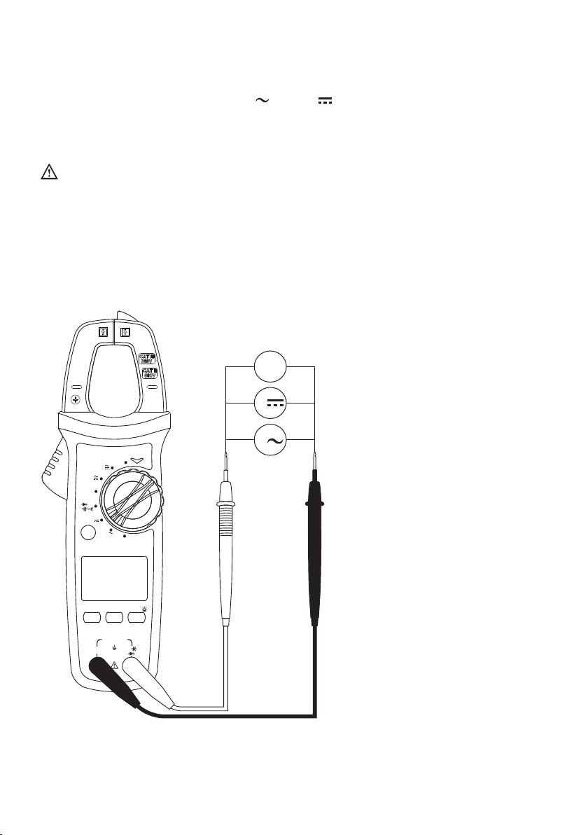
1. Select the corresponding function V(AC) or V (DC)
2. Insert the red test lead into the positive (+) jack, and the black into the COM jack.
3. Connect test leads to the measured circuit.
NOTE:
•Do not input voltage above 600V to prevent electric shock or damage.
The input impedance of each range scale is 10MΩ, this load eect in high resistance
measurement may cause error. If the input impedance is lower the than 10kΩ, the error
can be ignored (<0.1%).
•Be cautious to avoid electric shock when measuring high voltage.
•Please check the functions by applying a known voltage before use.
SELECT
REL/ZERO
MAX/MIN HOLD/
True RMS
AC/DC CLAMP METER
NCV
400A
40A
V
V
Hz%
Hz
OFF
Ω
V
Hz
COM
CAT III 300V
CAT III 600V
Ω
V
Hz
V
Tabla de contenidos
Otros manuales de Instrumento de medición de TTI

TTI
TTI PSA2702 Manual de usuario

TTI
TTI PSA2701T Manual de usuario

TTI
TTI 1604 Manual de usuario

TTI
TTI FTE6100 Manual de usuario

TTI
TTI LD300 Manual de usuario

TTI
TTI PFM3000 Manual de usuario

TTI
TTI FTE-7000A Manual de usuario

TTI
TTI TTIDM1000VAR Manual de usuario

TTI
TTI PROFESSIONALS TTICM1000V Manual de usuario
Manuales populares de Instrumento de medición de otras marcas

Endress+Hauser
Endress+Hauser Proline Promag 50 Especificaciones técnicas

Siemens
Siemens SITRANS F Coriolis FCT030 Manual de lista de piezas

KLINGER
KLINGER CMF V Series Manual de usuario

EXFO
EXFO FTB-2 Manual de operación y mantenimiento

Keysight
Keysight M8290A Manual de usuario

ADTEK
ADTEK MW-5 Manual de usuario