SVC WIRELESS EXTERNAL DATA INTERFACE 4 CHANNEL USER MANUAL REVISION 1.0
Table Of Figures
Figure 1 WEDI-4 Top iew Showing Built-In PAR Sensor ........................................................................................... 1
Figure 2 WEDI-4 Side iew Showing External Sensor Inputs – Pyranometer (SPN-1), and Thermistor (T) ....... 1
Figure 3 Using The WEDI-4 In The Field With arious Sensors .................................................................................. 2
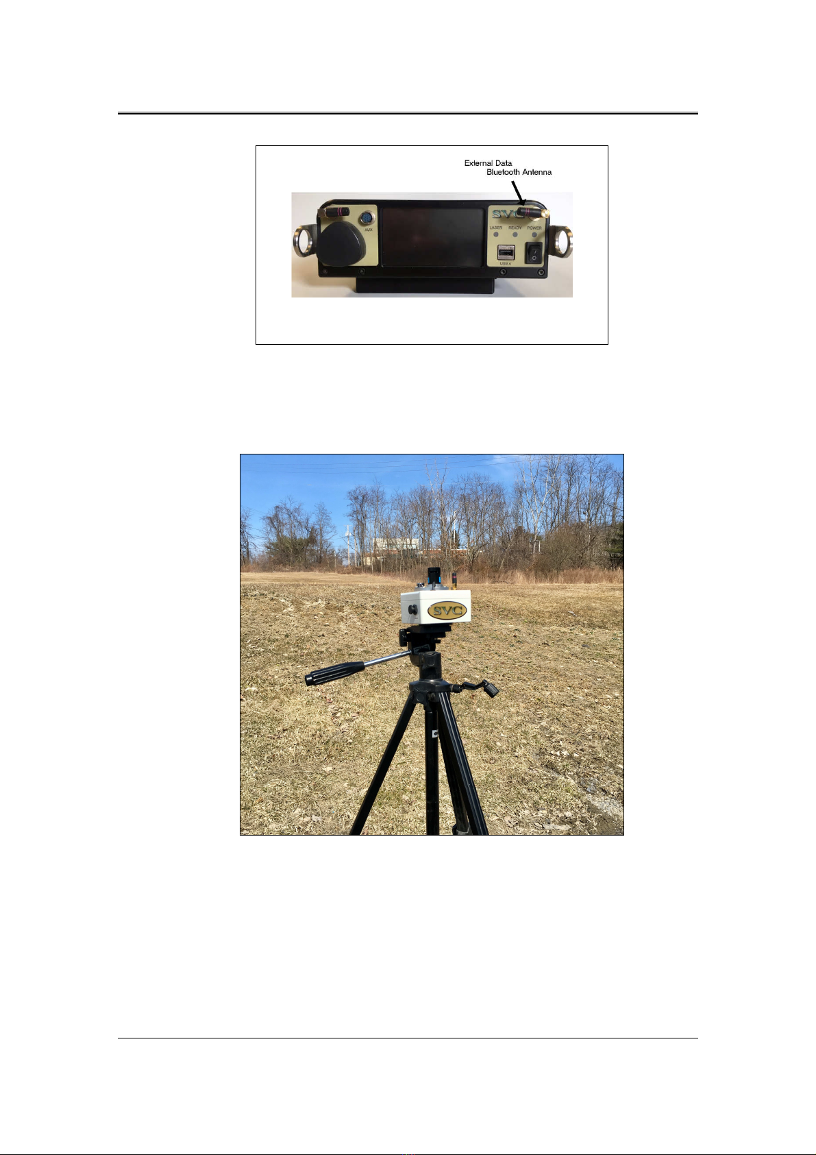
Figure 4 i-Series External Data Bluetooth Antenna Location ......................................................................................... 3
Figure 5 WEDI-4 Mounted Securely To A Tripod ........................................................................................................... 3
Figure 6 WEDI-4 Power Switch ........................................................................................................................................... 4
Figure 7 WEDI-4 Unique Bluetooth Address Tag, Chassis Bottom .............................................................................. 5
Figure 8 PC Software Pairing ................................................................................................................................................. 5
Figure 9 LCD Pairing Process, Before Turning On The WEDI-4 ................................................................................. 6
Figure 10 LCD Pairing Process, Completed ....................................................................................................................... 6
Figure 11 Waiting for the Initial Reference Scan ............................................................................................................... 7
Figure 12 LCD Indicating Downwelling Radiance Is Currently Down 3 Percent vs Reference ............................... 8
Figure 13 LCD Indicating Downwelling Radiance Is Currently Up 10 Percent vs Reference .................................. 8
Figure 14 PC Software WEDI Controls Example ............................................................................................................. 9
Figure 15 PC Software New Main Screen Buttons and External Data Display Fields ............................................. 10
Figure 16 External Data Display After Reference Scan .................................................................................................. 11
Figure 17 External Data Display After Ext Data Scan ................................................................................................... 11
Figure 18 External Data Display After Target Scan - Cloud Cover! ............................................................................ 11
Figure 19 WEDI-4 Battery Charging Port ........................................................................................................................ 12
Figure 20 WEDI-4 Battery Charger ................................................................................................................................... 12
Figure 21 WEDI-4 Battery oltage Displayed On Channel 5 ....................................................................................... 13
Figure 22 Battery oltage Measurement - Across SPN-1 Connector Pins 2 and 3 ................................................... 14
Figure 23 Battery Replacement – Opening The Unit ...................................................................................................... 15
Figure 24 Battery Replacement - Connector J2 "BATT" Partially Removed ............................................................. 16
Figure 25 Battery Replacement - Old Battery Prepared For Removal ......................................................................... 16
Figure 26 WEDI-4 Battery With Foam Tape Applied .................................................................................................... 17