Sirona SA7009 Manual de usuario

SIRONA HEMLOCK INFRARED SAUNA
OWNER’S MANUAL
SA7008/SA7009
Ver. 9/19
Please Do Not Hesitate to
Contact Our Consumer Hotline
at 800-759-0977
with Any Questions That May
Arise During Assembly or
Use of This Product!
SA7009
4-Person with 9 Carbon Heaters
SA7008
3-Person with 8 Carbon Heaters

2
ASSEMBLY TIPS & WARNINGS
PARTS IDENTIFIER
ASSEMBLY INSTRUCTIONS
ENJOYING YOUR SAUNA
HEALTH & SAFETY WARNINGS
CLEANING & MAINTANENCE
TROUBLESHOOTING GUIDE
REPLACEMENT PARTS
WARRANTY INFORMATION
3
4
5-9
10
11
12
13
13-14
15-16
17
TABLE OF CONTENTS
The information contained in this manual is subject to change without notice.
Les informations contenues dans ce manuel peuvent être modiées sans préavis.
If you would like a French version of this manual, please contact
Si vous voulez une version française d’un manuel, s'il vous plaît contacter
notre service à la clientèle au 800-759-0977 ou custserv@splashnetxpress.com
OPERATION INSTRUCTIONS
SAUNA USE DISCLAIMER 14

3
• Before you begin, read all assembly instructions and safety warnings carefully.
• This sauna requires at least 2 adults to complete assembly.
• Remove all of the contents from boxes and verify that you have all of the parts shown on the Parts
Note: Some parts may be pre-installed or pre-assembled.
may not look exactly like your product.
• Retain this Owner’s Manual for future reference.
ELECTRICAL REQUIREMENTS
• We recommend consulting a licensed electrician and checking local ordinances before installing
ANY sauna.
• These saunas require a 20 amp receptacle and a 20 amp circuit breaker. Note: Electrical modi -
•These saunas requires a dedicated circuit - No other appliances should share the same outlet
with the sauna.
CHOOSING A LOCATION
• This sauna should only be placed INDOORS on a dry, level surface.
• There should be a minimum of 5 inches clearance between the sauna and any wall.
• Make sure the main power cord will reach the outlet and remains easy to access.
• The sauna should only be used in a dry location as moisture will damage the wood and electrical
components.
combustible materials.
ASSEMBLY TIPS & WARNINGS

4
FRONT GLASS DOOR RIGHT SIDE PANEL BACK PANEL LEFT SIDE PANEL
OXYGEN IONIZER HARDWARE
PHILLIPS HEAD
SCREWDRIVER STEP LADDER
BENCH SUPPORT
HEATER PANEL DOOR HANDLE TOWEL HOOK CONTROL PANEL
MOOD LIGHTING
REMOTE
ROOF ROOF COVER FLOOR
FLOOR
HEATER COVER BENCH SEAT
PARTS IDENTIFIER (NOT TO SCALE)
1/16”wood
veneer
The parts identied above, unless otherwise indicated, are the main components used for assembly.
Other pre-assembled parts are listed on PAGE 15 & 16.
Refer to REPLACEMENT PARTS (PAGES 15 & 16) to determine the correct part number when ordering replacements.
4
9/19
Illustrations Not to Scale
For replacement parts please call 800-759-0977.
MOOD LIGHTING
BACKREST
1 2 3 4 5
ADDITIONAL EQUIPMENT
REQUIRED:
16 17 18 19
11 12 13 14 15
6 7 8 9 10
ADDITIONAL EQUIPMENT
REQUIRED:
Individual pc
breakdown
on Pg. 16
Pre-installed
FRONT RIGHT PANEL
Pre-installed
SIDE WALL
GLASS PANEL
20
If you are experiencing issues with your sauna or need
replacement parts, please have the following information
available when calling Customer Service at 800-759-0977:
• Date & Proof of Purchase • Model/SKU number
• Image of the metal plate mounted on back of sauna by plug
• Quality images of issue/concern (preferabbly in PDF format)
• Clear description of the issue
ASSEMBLY INSTRUCTIONS
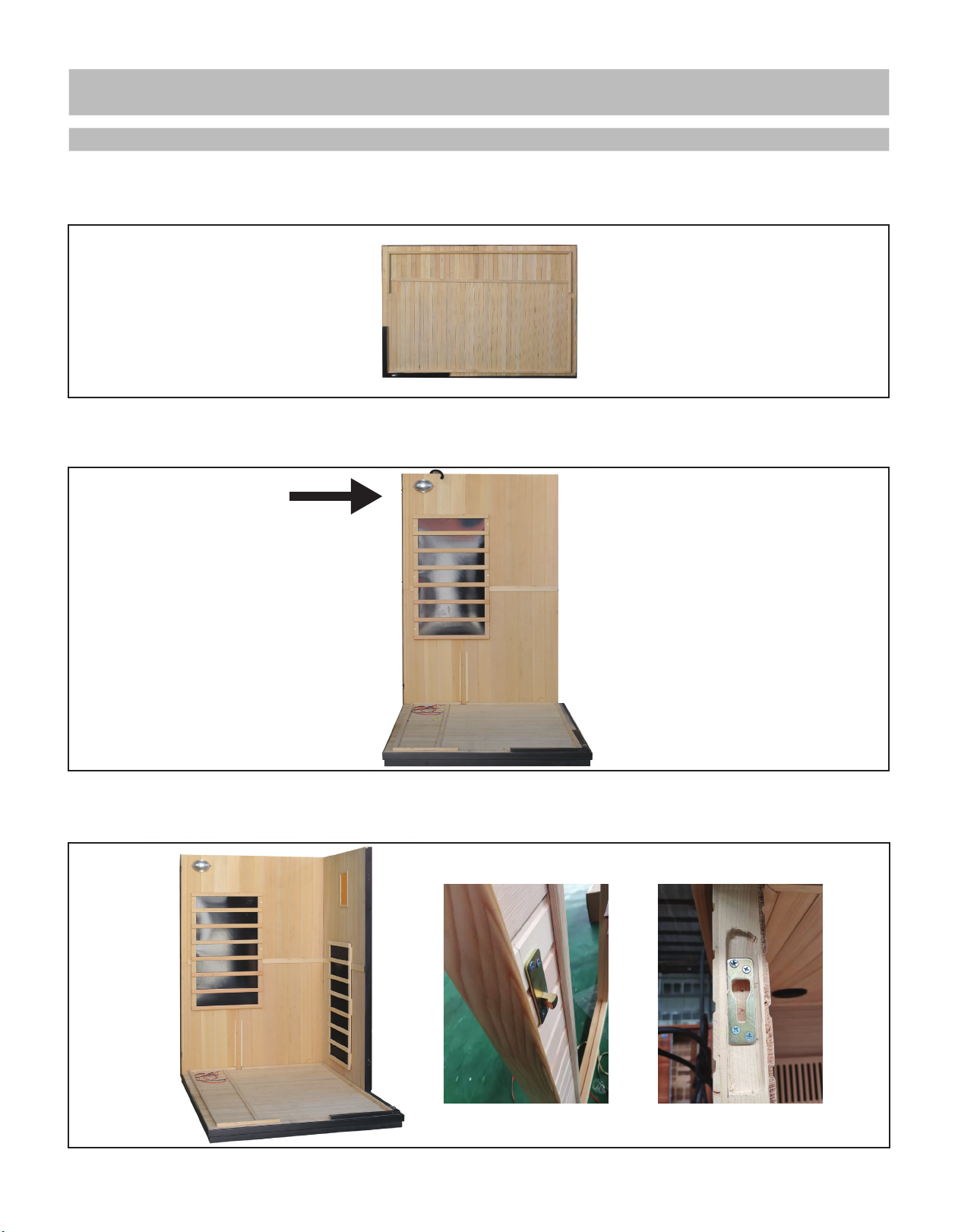
1. Begin assembly by determining an appropriate location for your sauna – see ASSEMBLY TIPS & WARNINGS
for details. Place the FLOOR PANEL on the oor in this location.
3. Place the FRONT RIGHT WALL PANEL on the FLOOR in the same manner and insert the INNER WALL CONNECTORS
on the side into the three corresponding holes on the RIGHT SIDE PANEL, then push down to lock panels together.
5
2. Place the RIGHT SIDE WALL PANEL on the FLOOR PANEL, lining up the SIDE PANEL against the oor trim
piece on the backside of the FLOOR.
NOTE: Oxygen Ionizer
will be installed in later Step 14

ASSEMBLY INSTRUCTIONS (CONT.)
6. Place the FLOOR HEATER COVER on the FLOOR PANEL. Once heater wires are connected and BENCH SUPPORT
is installed, use six 1-1/2” (40mm) SCREWS to attach HEATER COVER to FLOOR.
5. Place the LEFT SIDE WALL PANEL on the FLOOR in the same manner and buckle it to the BACK WALL PANEL.
6
4. Place the BACK WALL PANEL on the FLOOR as shown and make sure it ts snugly against the RIGHT SIDE
WALL PANEL with wall titng into groove and trim overlapping wall, then engage buckles.
Place ring over knob
and snap buckle closed
The LEFT SIDE WALL has a glass
panel that will need to be
installed next to it and attached
to FLOOR and ROOF in Step 10B
and Step 11.
TIP: You may need to move
FLOOR HEATER COVER in order
to make it easier to insert screws
in bottom of wall panel in
Step 10, so DON’T attach the
HEATER COVER to FLOOR until
after Step 10 is completed.
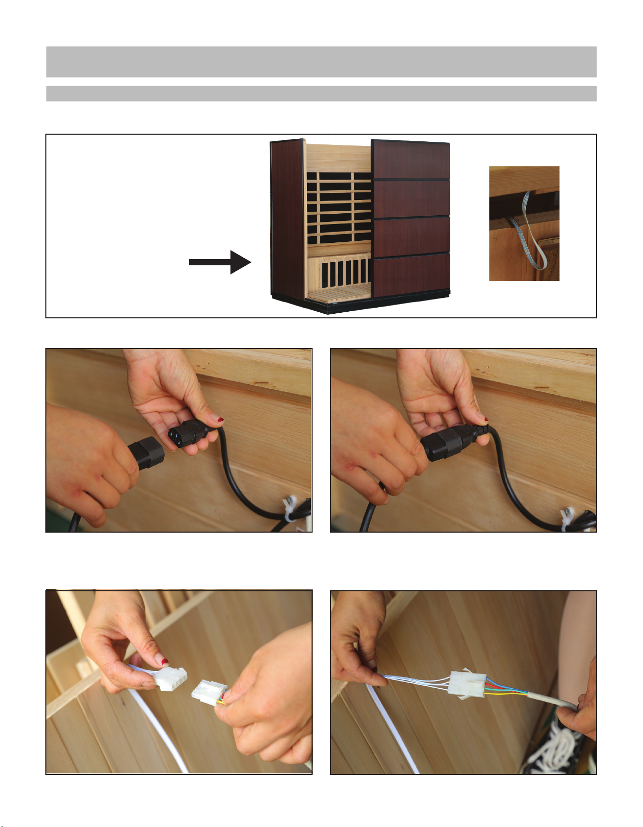
7. Install the BENCH SUPPORT HEATER PANEL between side walls by sliding into two trim pieces on each wall.
9. Connect the white MOOD LIGHTING bench plugs together. Make sure they click together tightly. Then place
the BENCH SEAT with bottom back wood strip over board on BACK WALL PANEL. Use two 2” (50 mm)
SCREWS to attach bench through pre-drilled holes.
ASSEMBLY INSTRUCTIONS (CONT.)
8. Connect the black oor heater plug and bench heater plug snuggly into the black plugs from BACK WALL PANEL.
7
NOTE: there will be a notch in
bottom of BENCH SUPPORT to
run black plug from FLOOR
HEATER through (see below),
so it’s not pinched. There will
also be one on top for white
MOOD LIGHTING wire.

ASSEMBLY INSTRUCTIONS (CONT.)
11. Attach the SIDE WALL GLASS to ROOF using two 3/4” (20mm) SCREWS and BLACK PLASTIC WASHERS
through glass. Snap four METAL CAPS onto four plastic washers just installed. Attach the GLASS DOOR HINGES
to frame using six 1” (25mm) SCREWS. Use pre-drilled holes in frame, so door aligns properly.
8
12. Connect the heater cable plugs, control panel wires, and mood lighting on the roof to the corresponding wire
connections coming up through walls and control panel roof hole. Make sure all wires are mated and connected tightly.
10B. Slide the SIDE WALL GLASS into the
slot on LEFT SIDE WALL and FLOOR. Attach
to FLOOR using two 3/4” (20mm) SCREWS
and BLACK PLASTIC WASHERS through glass.
10A. Lift the ROOF above the sauna and place on top of walls, feeding the control panel and heater cables through
the corresponding holes. Secure the ROOF and FLOOR, from interior, with four 1-1/2” (40mm) SCREWS, using
pre-drilled holes, two at top of wall panels and two at bottom (location is indicated by arrows below).
BLACK PLASTIC WASHERS
and METAL CAPS used
on these SCREWS
TIP: This is a two person job.
Have someone hold door in
place while you insert and
tighten screws.
12B. Feed the main power cable through hole in ROOF
and plug securely into receptacle on back of POWER
SUPPLY box. Place the ROOF COVER on top of ROOF and
secure with 12-14 3/4” (20mm) SCREWS.

ASSEMBLY INSTRUCTIONS (CONT.)
15. Attach the DOUBLE TOWEL HOOK with two 5/8” (16mm) SCREWS. Note: attaching hook is optional,
but if you do, consider the position carefully before driving any screws into the sauna interior.
14. Remove the back cover of the OXYGEN IONIZER by turning it as indicated. Unwrap and install the fragrance
patch, then reattach the back cover. Attach the OXYGEN IONIZER in the designated position with two 5/8”
(16mm) SCREWS. Plug the power cable into the OXYGEN IONIZER as shown.
The assembly of your sauna is now complete.
Please review the Operation Instructions and Health & Safety warnings before using your sauna.
To ensure years of trouble-free use, follow the Cleaning & Maintenance guidelines carefully.
9
CONGRATULATIONS!
16. Plug the main power cable into a dedicated outlet.
Note: No other appliances should share the same electrical outlet or circuit with this sauna.
13. Attach the DOOR HANDLE to the GLASS DOOR by assembling together using two 1-1/2” (40mm) SCREWS as shown.

OPERATION INSTRUCTIONS
SAUNA CONTROL PANEL -
MAIN SCREEN
1. Press POWER (bottom right button) to turn ON Control Panel. This will open Main Screen.
3. Select °C or °F and set the desired TEMPERATURE with the (+) and (-) buttons.
4. Set the desired TIME with the (+) and (-) buttons.
6. After your sauna session, press POWER (top left on screen) to turn OFF the sauna.
7. Press INSIDE or OUTSIDE to turn ON or OFF the corresponding light.
1. Press ION to release negatively charged ions to purify the air.
2. Press O3 to disinfect the air with ozone. 10
OXYGEN IONIZER
6. Power
Return to Last Screen
Home Screen
Volume
3. Set °C or °F
Main
Screen
3. Set
Temperature
7. Lights (Inside & Outside)
4. Set Time
8. Secondary Screen
5. Temperature &
Time Readings
2. Heater Switch
2. Press center Heater Switch to turn Sauna Heater Panels ON or OFF .
8. Use bottom right button to get to SECOND SCREEN for music and color therapy light controls.
5. When the TIME reaches 00, the heaters will turn OFF automatically.
1. Use the remote control to make adjustments to interior light color and intensity.
INTERIOR MOOD LIGHTING (this is NOT Color Therapy Light, see above)
Reset
TUNER - Use buttons to select AM and FM radio signal (FM1, FM2, FM3, AM1 or AM2), scroll through
channels (<>), or auto seek (AMS). Channels can be saved in P1- P6.
BLUETOOTH - Use touch controls to select and play music once connected to source.
CALENDAR - Use arrow buttons on right side of screen to set date and time, then press SAVE.
9. USB - Can be used with thumb drive only. Will NOT activate with any other input. Best to use Bluetooth for music.
1. Press ON or OFF in top white bar.
2. Press cycled color, or individual color desired,
using color buttons.
3. Use dimer switch to control brightness.
4. Cycle switch can be used to go through colors
and select.
SECONDARY SCREEN - Use button to select function
COLOR THERAPY CONTROL PANEL
(use LED COLOR button to reach controls)
3. Dimer Switch
1. On/O Switch
2. Color Selection
3. Color Cycle
Interior Mood Lighting
can be controlled by this remote
ONLY, NOT control panel.
1. Power
9. USB
1. Press larger black button on roof control to power on,
adjust with smaller black button.
STAR LIGHTS (this is NOT Color Therapy Light, see above)
Este manual sirve para los siguientes modelos
1
Tabla de contenidos
Manuales populares de Producto de plomería de otras marcas

Weka
Weka 506.2020.00E Instrucciones de funcionamiento

Kohler
Kohler K-6228 Instrucciones de montaje

UBERHAUS DESIGN
UBERHAUS DESIGN 75175017 Manual de usuario

American Standard
American Standard DetectLink 6072121 Manual de usuario

Uponor
Uponor Contec TS Manual de usuario

Pfister
Pfister Selia 49-SL Manual de usuario


