ShoreStation ShoreScreen CS270-102-7B Manual de usuario


Document Number: 0004593
Rev: 1 Page 2
Introduction
The ShoreScreen Power Curtain system is designed to be assembled to a boathouse structure. The assembly process involves leg
bolts and mounting brackets to the boathouse, hanging the curtain sides, attaching the corner components, and pairing the wireless
remotes with the controller.
The assembly process explained in this document should be performed by a qualified ShoreStation technician who understands the
proper techniques and applications of the equipment used during the assembly process.
Safety Definitions
Safety messages are presented throughout this document and labels affixed to the product. The messages alert you to potential
hazards to you and/or property. The signal words DANGER, WARNING, and CAUTION are preceded by an alert symbol and
communicate the severity of potential hazard. The severity of each type of message is defined as follows:
DANGER indicates a hazardous situation which, if not avoided, will result in death or serious injury.
WARNING indicates a hazardous situation which, if not avoided, could result in death or serious injury.
CAUTION, used with the safety alert symbol, indicates a hazardous situation which, if not avoided, could result in minor or moderate
injury.
WARNING
DO NOT ATTEMPT TO ASSEMBLE THIS SYSTEM WITHOUT FIRST STUDYING THIS MANUAL AND
INFORMATION ON LABELS INCLUDED WITH THE SYSTEM. FAILURE TO DO SO CAN LEAD TO IMPROPER
OPERATION RESULTING IN SERIOUS PERSONAL INJURY AND/OR PRODUCT DAMAGE. IF YOU HAVE
FURTHER QUESTIONS AFTER REVIEWING THIS INFORMATION, CONTACT A SHORESTATION
REPRESENTATIVE AT (800) 859-3028.

Document Number: 0004593
Rev: 1 Page 3
Table of Contents
Click on the section title to jump to the section:
Introduction ......................................................................................................... 2
Safety Definitions................................................................................................. 2
Safety Instructions ............................................................................................... 3
Preparation .......................................................................................................... 4
Curtain Assembly Instructions ............................................................................. 4
Pairing the ShoreScreen Wireless Controls with your Boat Lift......................... 14
Pairing Existing FlexPower Controls................................................................... 15
Troubleshooting................................................................................................. 17
Safety Instructions
WARNING
Never install or work on the equipment without first verifying that the A/C power supply (if present) is protected by a functioning
Ground Fault Circuit Interrupt (GFCI) in accordance with National Electric Code section 210.8 and any additional local code requirements.
Disconnect all A/C power from the dock before installing or working on the equipment.
Assembly and installation of this system my require working over water. Always wear a personal floatation device (PFD) when working
over the water.
Remove any metallic objects from your person before working with DC or AC electrical components.
Always wear proper personal protective equipment such as safety glasses, gloves, hardhats, and clothing.
Never work alone and observe safe lifting practices such as team lifting and proper lifting posture.
Never pair the remotes to operate more than one boat lift. Doing so could cause unintended operation and result in injury and product
damage.
The system should only be run if the operator has clear vision of the lift equipment and its surrounding location.
Do not modify the equipment unless you have received direct written approval from the manufacturer (ShoreStation).

Document Number: 0004593
Rev: 1 Page 4
Preparation
Assembling the curtain takes at least two people and will require lifting and attaching components to the boathouse, but should not
affect the integrity of the structure.
Tools Required:
SAE and Metric Hex Keys (Allen Wrenches)
SAE Sockets and Wrenches
Cordless Power Drill
5/16 Power Nut driver
#3 Square drive
Curtain Assembly Instructions
1 –Organize Parts
Unroll the curtains, open the hardware box and bag, and sort the hardware and other contents by size.
2 –Attach the Brackets
All boathouses are different so the best bracket method depends on the boathouse. 1- bolt the clamp brackets
to the inside of the frame. 2- bolt the clamp brackets to the pile mounts. 3- bolt the clamp bracket to
crossbeams. Evenly space the clamps on both sides of the boathouse and open the clamps if they aren’t
already open. (Lag bolts are not included)
Document Number: 0004593
Rev: 1 Page 5
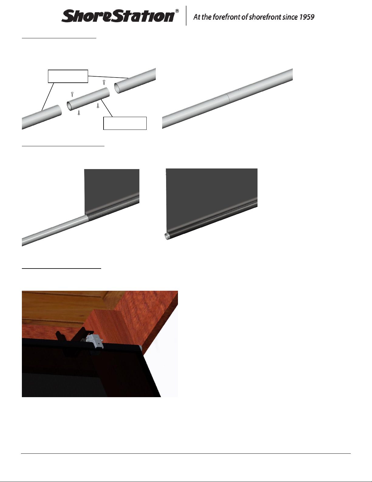
3 –Connect Tube Splices
Use a #3 square bit to drill the self-tap screws through the side tubes and splice as shown. There is a bundle of
side tubes and a bundle of end tubes, be sure to use the side tubes.
4 –Slide Tubes into Curtain
Slide the connected side tubes into the top of the side curtain and the end tubes into the top of the end
curtains as shown.
5 –Hang the Side Curtains
Start on the ends and put the top curtain tubes in the curtain clamps, and push the pin through the clamps to
secure the curtain. Then, repeat with all other clamps.
Long tubes
Tube splice

Document Number: 0004593
Rev: 1 Page 6
Make sure the plastic keder strip is facing up and is toward the outside of the boathouse as shown below.
6 –Slide Tubes into Curtain
Slide the connected side tubes into the bottom of the side curtain and the end tubes into the bottom of the
end curtains as shown.
7 –Connect Splice to Roll Tube
Use the 1-1/4” machine screws to join one side roll tube with one roll tube splice as shown. 24’ and 26’
curtains have one splice on each side and the 28’ curtain and bigger has 2 splices on each side.
Outside of boathouse
Keder strip
Inside of boathouse
Curtain
Roll Tube Splice
Roll Tube

Document Number: 0004593
Rev: 1 Page 7
8 –Slide on the Roll Tubes
Slide the side roll tubes onto the keder strip on the side curtains.
9 –Connect the Roll Tubes
Use the 1-1/4” machine screws to join the side roll tubes as shown.
10 –Connect the End Curtains to the Side Curtains
Slide the corner splices into the top on both sides of the end curtain tubes.
Corner splice

Document Number: 0004593
Rev: 1 Page 8
Then, slide the top corner splices into the side curtain top tubes. You may have to pull out the pin and pull
down on the side curtain tube as you insert the corner splice. (Push pin back into curtain clamp)
11 –Slide on the Roll Tubes
Slide the roll tubes onto the keder strip on the end curtains.
12 –Install the Corner Drives
Insert the side drive shaft into the bushing and line up the holes. Then slide the drive shaft and bushing into
the side curtain roll tube, line up the holes again, insert the 1-1/4” machines screws, and tighten. Also, slide
the end drive shaft into the end curtain roll tube, line up the holes, insert the screws, and tighten (as shown
below). Do the same on the opposite corner.
Side
curtain
End
curtain
Bushing
Side drive shaft

Document Number: 0004593
Rev: 1 Page 9
13 –Install Idler Corners
Slide the idler corner shafts into the roll tubes of the side curtain and end curtain. Line up the holes, insert the
1-1/4” machine screws, and tighten (as shown). Do the same on the opposite corner.
14 –Self-tap the Corner Splices
Adjust the top corner splices and curtain as needed and self-tap the screws through the curtain as shown. Tap
the screws closest to the corner first, then the screws through the curtain.
End
curtain
Side
curtain
Corner Drive
Corner Drive
Idler Corner
Idler Corner
Top View of ShoreScreen

Document Number: 0004593
Rev: 1 Page 10
Slide the corner splice into the lower tube of the side curtain and end curtain on all corners. Adjust as needed,
match the corner above, and self-tap the screws through the curtain as shown.
15 –Splice Cover
Snap on the plastic splice cover to the roll tube.
16 –Relay Placement
Place the relay assembly on the curtain tube, about half way down the curtain on the power side of the
boathouse, and use the self-tap screws to secure it to the top side tube. The relay assembly may have to be
adjusted depending on length of harness needed to reach the motors.
The upper limit switch automatically stops the curtain from rolling too high and into the relay assembly box. If
necessary it may be adjusted to prevent damage.
Self-tap screw
Self-tap screw
Upper Limit
Switch
Este manual sirve para los siguientes modelos
11
Tabla de contenidos


