COVERPRO 56184 Instrucciones de montaje

Visit our website at: http://www.harborfreight.com
Email our technical support at: [email protected]
WARNING! Do not start or operate any internal
combustion engine inside or near Shed.
Owner’s Manual & Safety Instructions
Save This Manual Keep this manual for the safety warnings and precautions, assembly,
operating, inspection, maintenance and cleaning procedures. Write the product’s serial number in the
back of the manual near the assembly diagram (or month and year of purchase if product has no number).
Keep this manual and the receipt in a safe and dry place for future reference. 19c
When unpacking, make sure that the product is intact
and undamaged. If any parts are missing or broken,
please call 1-888-866-5797 as soon as possible.
Copyright© 2019 by Harbor Freight Tools®. All rights reserved.
No portion of this manual or any artwork contained herein may be reproduced in
any shape or form without the express written consent of Harbor Freight Tools.
Diagrams within this manual may not be drawn proportionally. Due to continuing
improvements, actual product may differ slightly from the product described herein.
Tools required for assembly and service may not be included.
Read this material before using this product.
Failure to do so can result in serious injury.
SAVE THIS MANUAL.
Page 2 For technical questions, please call 1-888-866-5797. Item 56184
Table of Contents
Safety ......................................................... 3
Specifications ............................................. 4
Assembly .................................................... 4
Maintenance .............................................. 10
Parts List.................................................... 11
Warranty .................................................... 12
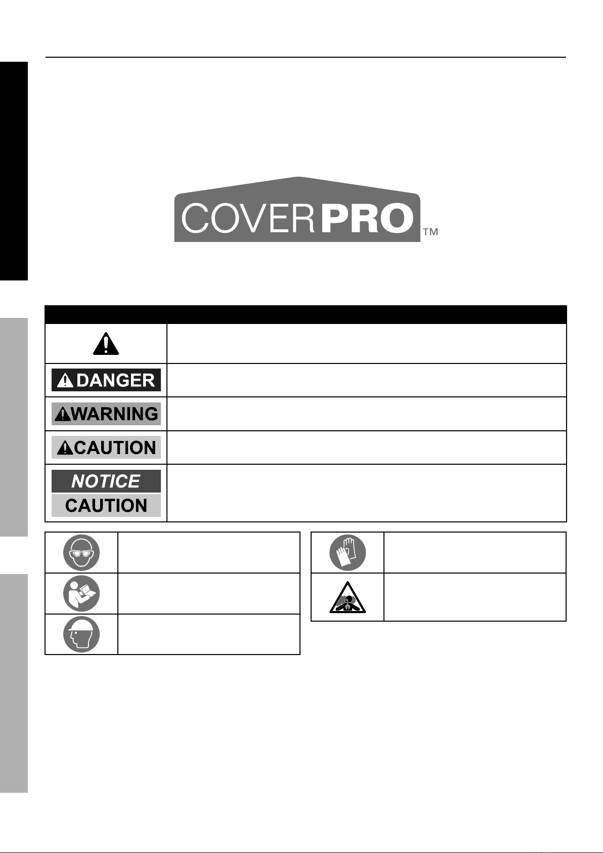
WARNING SYMBOLS AND DEFINITIONS
This is the safety alert symbol. It is used to alert you to potential
personal injury hazards. Obey all safety messages that
follow this symbol to avoid possible injury or death.
Indicates a hazardous situation which, if not avoided,
will result in death or serious injury.
Indicates a hazardous situation which, if not avoided,
could result in death or serious injury.
Indicates a hazardous situation which, if not avoided,
could result in minor or moderate injury.
Addresses practices not related to personal injury.
WARNING marking concerning Risk
of Eye Injury. Wear ANSI-approved
safety goggles with side shields.
Read the manual before
assembly and/or use.
WARNING marking concerning
Risk of Head Injury. Wear hard hat
during assembly and service.
WARNING marking concerning Risk
of Hand Injury. Wear heavy-duty work
gloves during assembly and service.
WARNING marking concerning
Risk of Respiratory Injury.
Operate engine OUTSIDE and far
away from windows, doors, and vents.
SAFETY MAINTENANCE
ASSEMBLY

Page 3For technical questions, please call 1-888-866-5797.Item 56184
IMPORTANT SAFETY INFORMATION
Read all safety warnings and instructions.
Failure to follow the warnings and instructions may result in serious injury.
Save all warnings and instructions for future reference.
The warnings, precautions, and instructions discussed in this instruction manual cannot cover all possible
conditions and situations that may occur. It must be understood by the operator that common sense
and caution are factors which cannot be built into this product, but must be supplied by the operator.
Assembly Precautions
1. Do not assemble in windy conditions.
2. Assemble and install only on
flat, level, hard surface.
3. Assemble and anchor only according to
these instructions. Improper assembly or
inadequate anchoring can create hazards.
4. Check for utility lines, tree branches and
other structures before assembling.
5. Verify that installation surface has no
hidden utility lines before anchoring.
6. Wear ANSI-approved safety goggles,
heavy-duty work gloves and hard hat
during assembly and service.
7. Keep assembly area clean and well lit.
8. Keep bystanders out of the area during assembly.
9. Do not assemble when tired or when under
the influence of drugs or medication.
10. Product capabilities apply to properly and
completely assembled product only.
Use Precautions
1. CARBON MONOXIDE HAZARD
Using an engine inside Shed
CAN KILL YOU IN MINUTES.
Engine exhaust contains
carbon monoxide. This is a poison
you cannot see or smell.
NEVER use an engine inside Shed,
EVEN IF cover is open.
Only use an engine OUTSIDE and far away from
Shed.
2. DO NOT USE IN HIGH WIND. Remove cover
if harsh weather or heavy rain threatens.
3. For temporary use only.
Do not use for long-term shelter.
4. Do not use as tent. Does not meet tent
flammability standards. Do not use grill, heater,
or ignition sources inside or near cover.
5. Do not allow snow, rainwater or debris
to accumulate or pool on cover.
6. Do not hang objects from any part of the Shed.
7. This product is not a toy. Do not allow
children to play with or near this item.
8. Use as intended only.
9. Inspect regularly, tighten all loose hardware
and loose ropes, and secure all loosened
anchors. If any parts are damaged, bent, or
stretched, they must be replaced. Hardware
may loosen during normal operation stresses.
Loose hardware or damaged/altered parts will
compromise the structural integrity of this product.
10. Maintain product labels and nameplates.
These carry important safety information.
If unreadable or missing, contact
Harbor Freight Tools for a replacement.
SAVE THESE INSTRUCTIONS.
SAFETYMAINTENANCE ASSEMBLY

Page 4 For technical questions, please call 1-888-866-5797. Item 56184
Specifications
Overall Dimensions 10′ W x 10′ L
Center Height 8′ 1″
Side Height 6′ 3″
Tubing Diameter 1.321" Dia x 0.039" T
Assembly Instructions
Read the ENTIRE IMPORTANT SAFETY INFORMATION section at the beginning of this
manual including all text under subheadings therein before set up or use of this product.
TO PREVENT SERIOUS INJURY:
Do not leave this product partially assembled. Assemble this product completely at one time.
Note: At least 3 workers are required for assembly. Before starting assembly, review the instructions and make
sure there is enough time and the proper tools available to properly assemble.
Finger tighten all connections until assembly is done. Assemble on a flat, level surface.
1. Gather the Bolts and put into two piles:
a. Bolt M6 x 40 (12) will be used to
assemble the Bottom Rails (9).
b. Bolt M6 x 50 (13) will be used to assemble
the Top Rails (2) and Rafters (1).
Assemble Roof
Note: Unless where otherwise noted, this product’s assembly is done using
slip fit construction. Make sure all parts seat completely and securely. A rubber
mallet (sold separately) can be used to gently tap parts in place to ensure a tight fit.
1. Lay out Roof parts.
5
2
6
2
5
1 1 1
11 1
3
2
4
2
3
5
2
6
2
5
SAFETY MAINTENANCE
ASSEMBLY

Page 5For technical questions, please call 1-888-866-5797.Item 56184
NOTICE: To prevent damage to the material, make sure all hardware is installed
with Bolt facing cover and Nuts facing inside, away from cover.
2. Connect four Rafters (1) to two 3-Way Rail
Connectors (3) using four Bolts (13) and Nuts (14).
3. Connect two Rafters (1) to one 4-Way Rail
Connector (4) using two Bolts (13) and Nuts (14).
4. Connect two Top Rails (2) to tie the 4-Way
Rail Connector assembly and two 3-Way
Rail Connector assemblies together. Slide
the Rails into the Connector openings
and push all the way in to secure.
34
3
1
1
1
1
1
1
2
2
Nuts (14)
Bolts (13)
Bolts (13)
Bolts (13)
Nuts
(14) Nuts
(14)
3
4
3
5. Connect four 3-Way Corner Connectors, one
to each of the four outside corner legs.
6. Connect two 4-Way Center Connectors, one
to each end of the inside center legs.
7. Using four Top Rails (2), connect one between
each Corner and Center assembly, tying them
together. Slide the Rails into the Connector
openings and push all the way in to secure.
52
6
5
25
6
5
2
2
Assemble and Attach Legs
1. Attach four Corner Feet (7) to
the four corner Legs (2).
Corner
Foot (7)
Leg (2)
2. Attach two Center Feet (8) to
the two center Legs (2).
Leg (2)
Center
Foot (8)
SAFETYMAINTENANCE ASSEMBLY

Page 6 For technical questions, please call 1-888-866-5797. Item 56184
4. Attach Corner Legs and Feet to the
four 3-Way Corner Connectors.
5. Attach Center Legs and Feet to the
two 4-Way Center Connectors.
NOTICE: To prevent damage to the material, make sure all hardware is installed
with Bolt facing cover and Nuts facing inside, away from cover.
6. Connect four Bottom Rails (9) between the
Center and Corner Legs using the Center
Clamps (11) and Corner Clamps (10).
a. For Center Legs: Place one Center Clamp (11)
on the front and one on the back of the
connection. Secure the Clamps using two
Bolts (12) and Nuts (14). Tighten.
Repeat for the other Center Leg.
b. For Corner Legs: Place one Corner Clamp (10)
on the front and one on the back of the
connection. Secure the Clamps using one
Bolt (12) and Nut (14). Tighten
Repeat for the other three Corner Legs.
Two Corner
Clamps (10)
Two Center
Clamps (11)
Nut
(14)
Nuts
(14)
Corner
Leg
Center
Leg
Bolt
(12)
Bolts
(12)
Corner
Leg &
Foot Center
Leg &
Foot
99
9
9
3-Way
Corner
Connector 4-Way
Center
Connector
SAFETY MAINTENANCE
ASSEMBLY

Page 7For technical questions, please call 1-888-866-5797.Item 56184
Square up the Frame
TO PREVENT SERIOUS INJURY:
Contact local utility companies to ensure that the installation area is free of pipes, cables,
and other hazards BEFORE choosing installation area or installing anchors.
1. Position the frame in the desired location,
making sure it is level and flat.
2. Measure between diagonal corners. These
measurements must be within 1″ of each other.
3. Measure across front and back. These
measurements must be 10' each.
4. If any measurements do not match, adjust the frame
and measure again until measurements match.
Anchor the Frame
WARNING! Anchor only according to these instructions. Improper assembly
or inadequate anchoring can create hazards.
CAUTION! To prevent tripping hazard, position Anchors toward
the interior of the frame, close to the Corner Feet.
1. Use a metal bar (sold separately) to thread the
Anchor (16) into the ground, until the loop at the
top of the Anchor extends just above the ground.
Note: When anchoring to concrete, use
Concrete Anchors (not included).
Metal Bar
Anchor
(16)
2. Insert the Wire Rope (17) through
the Anchor and Corner Foot.
3. Tighten the Wire Rope and secure it
using a Wire Rope Clamp (18). Tighten
the nuts on the Clamp evenly.
Wire Rope
(17) Interior
of Frame
Wire Rope
Clamp (18)
4. Repeat on the other corners.
Note: Center Feet may be anchored
to increase stability.
SAFETYMAINTENANCE ASSEMBLY

Page 8 For technical questions, please call 1-888-866-5797. Item 56184
Attach Roof
1. Stretch Top Cover (19) over the frame,
making sure it is centered.
2. From the inside, on one side of the Shed,
remove the Bottom Rails from the Clamps.
3. Insert the Rails into the pockets at the
bottom of the Shed wall and then reinsert
the Bottom Rails back into the Clamps.
4. Repeat on other side of Shed.
Pocket
Bottom
Rails
Ratchet Tie
Down (22)
Pocket
Strap
5. From the inside at the corners, thread the Straps through Ratchet Tie Down’s spindles.
Insert the “S” hook of the Ratchet into the hole in the Corner Feet.
Strap
Spindle
Ratchet Tie
Down (22)
Inside
6. Raise and lower the Ratchet Tie Down’s handles, alternating between
each corner, until straps are slightly tight with a little slack.
Inside
7. Repeat for the other three corners.
SAFETY MAINTENANCE
ASSEMBLY

Page 9For technical questions, please call 1-888-866-5797.Item 56184
Attach Front and Back Covers
1. Position Front Cover (20) so that zipper pulls are facing toward the outside. Make sure zippers are closed.
2. From inside, wrap the hook and loop straps around the Rails. Make sure to
connect all straps. Secure straps completely around the Rails.
Straps
Inside
3. Repeat for Back Cover (21).
4. From the inside, using a wrench (not included), tighten the Ratchet Tie Down’s
handles, alternating between each corner, until straps are snug.
5. Tighten all connections throughout the shed before use.
Do not overtighten.
SAFETYMAINTENANCE ASSEMBLY

Page 10 For technical questions, please call 1-888-866-5797. Item 56184
Maintenance
Procedures not specifically explained in this manual must
be performed only by a qualified technician.
TO PREVENT SERIOUS INJURY FROM PRODUCT FAILURE:
Do not use damaged products. If damage is noted, have the problem corrected before further use.
Inspection
MONTHLY, inspect the general condition of the Portable Shed. Check for:
• loose ratchet tie downs, anchors, tube connections, and rail clamps (tighten as needed),
• torn or frayed covers, ropes, or wire ropes,
• cracked, bent, or broken parts, and
• any other condition that may affect its safe operation.
Cleaning
1. Immediately remove any accumulated
debris from the cover with a broom, mop,
or other soft-sided instrument from the
outside. DO NOT use sharp instruments.
2. PERIODICALLY, clean cover with mild
soap and water. DO NOT use bleach
or harsh abrasive products.
PLEASE READ THE FOLLOWING CAREFULLY
THE MANUFACTURER AND/OR DISTRIBUTOR HAS PROVIDED THE PARTS LIST IN THIS MANUAL
AS A REFERENCE TOOL ONLY. NEITHER THE MANUFACTURER OR DISTRIBUTOR MAKES ANY
REPRESENTATION OR WARRANTY OF ANY KIND TO THE BUYER THAT HE OR SHE IS QUALIFIED TO
MAKE ANY REPAIRS TO THE PRODUCT, OR THAT HE OR SHE IS QUALIFIED TO REPLACE ANY PARTS
OF THE PRODUCT. IN FACT, THE MANUFACTURER AND/OR DISTRIBUTOR EXPRESSLY STATES
THAT ALL REPAIRS AND PARTS REPLACEMENTS SHOULD BE UNDERTAKEN BY CERTIFIED AND
LICENSED TECHNICIANS, AND NOT BY THE BUYER. THE BUYER ASSUMES ALL RISK AND LIABILITY
ARISING OUT OF HIS OR HER REPAIRS TO THE ORIGINAL PRODUCT OR REPLACEMENT PARTS
THERETO, OR ARISING OUT OF HIS OR HER INSTALLATION OF REPLACEMENT PARTS THERETO.
Record Product’s Serial Number Here:
Note: If product has no serial number, record
month and year of purchase instead.
Note: Some parts are listed and shown for
illustration purposes only, and are not available
individually as replacement parts.
SAFETY MAINTENANCE
ASSEMBLY
Tabla de contenidos
Otros manuales de Carpa de COVERPRO

COVERPRO
COVERPRO 56410 Instrucciones de montaje

COVERPRO
COVERPRO 63297 Instrucciones de montaje

COVERPRO
COVERPRO 59699 Instrucciones de montaje

COVERPRO
COVERPRO 58741 Instrucciones de montaje

COVERPRO
COVERPRO 62860 Instrucciones de montaje

COVERPRO
COVERPRO 59707 Instrucciones de montaje

COVERPRO
COVERPRO 62899 Instrucciones de montaje


