Shibuya Hoppmann L500A V2 Manual de instrucciones
TM
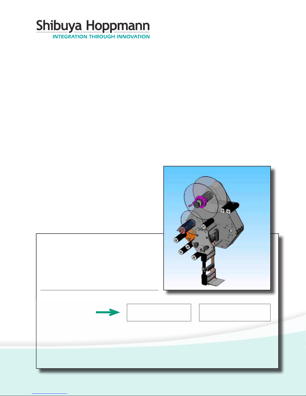
L500A V2 High
Speed Labeler
Installation/Maintenance
Manual
Publication Version, Revision 1, All rights reserved.
© 2011 Shibuya Hoppmann Corporation
13129 Airpark Drive, Suite 120 • Elkwood, Virginia 22718 • USA
Tel: (540) 829-2564 • Fax: (540) 829-1726 • E-mail: [email protected]
Duplication of this manual, in whole or in part, requires written consent of Shibuya Hoppmann Corporation.
Model Name: Model Inventory Number:
Refer all servicing to qualied personnel.
This manual is intended for use by qualied
mechanic and electricians who install or service
the L500A V2 High Speed Labeler.
Please copy this information from
the L500A V2 High Speed Labeler’s
serial plate.

L500A V2 High Speed Labeler Manual
2 3
About This Manual
Who Should Read
This manual is intended for those who need to install and/or operate the
label applicator. The manual is not intended to meet the training needs of
persons new to labeling; nor is it intended to meet the needs of person‑
nel who wish to completely overhaul the unit. These needs will require
assistance of experienced personnel and are outside the scope of this
manual.
Note:
Please carefully read this entire manual before operating your label ap‑
plicator.
Caution Symbols
Caution symbols and messages in this manual call attention to
and Messages
hazardous voltages, moving parts, and other hazardous conditions.
The exclamation point caution symbol denotes possible personal injury
and/or damage to the equipment.
The lightning bolt caution symbol denotes possible personal injury and/
or damage to the equipment from electrical hazards.
Quick Start
Equipment Improvements & Shibuya Hoppmann Corporation (SHC) continually improves its products, and reserves the right to change
DocumentRevisionsNotice ordiscontinuespecicationsanddesignsshowninthismanualwithoutnoticeandwithoutincurringobligation.
SHC has made every effort to verify the information contained in this manual, but reserves the right to correct
any error at the time of the manual’s next revision. This manual is subject to change without notice. 02/11

2 3
Quick Start
2 About This Manual
3 Table of Contents
6 TermsandDenitions
Description and
7 The Label Applicator
Specications
11 ApplicatorSpecications
Figures/Tables:
8 Figure 1‑1. Label Applicator
9 Figure 1‑2. Side View of L500A V2 Labeler
10 Figure 1‑3. Back View of L500A V2 Labeler
11 Table1‑1.ApplicatorSpecications
Safety Precautions
13 Warnings and Conditions
Figures:
13 Figure 2‑1. Additional Warning Labels
Applicator Installation
15 Unpacking and Inspection
15 Applicator Positioning
20 Remote Electrical Enclosure/Interface Panel
21 Power Supply
Figures/Tables:
16 Figure 3‑1. Correct/Incorrect Positioning
17 Figure 3‑2. Rotation Adjustment
18 Figure 3‑3. U‑Arm
19 Figure 3‑4. Adjustments for T‑Stand and U‑Arm
20 Figure 3‑5. Interface Panel
Applicator Setup
23 Label Threading
28 Light Tower (Optional)
29 Low Label Sensor (Optional)
30 Rewind Clutch Adjustment
31 Product Sensor
32 Lion LRD 2100 Label Sensor
35 Setting the Labeling System
37 Right‑Hand to Left‑Hand Conversion
Table of Contents
ChapterPage
1
2
3
4

L500A V2 High Speed Labeler Manual
4 5
Applicator Setup
Figures/Tables:
23 Table4‑1.LabelandWebSpecications
24 Figure 4‑1. Web Path/Label Threading Path
25 Figure 4‑2. Unwind Assembly/Installing New Labels
26 Figure 4‑3. Lockout Knobs and Nip Rollers
27 Figure 4‑4. Rewind Assembly/Threading
27 Figure 4‑5. Light Tower
28 Figure 4‑6. Low Label Sensor
30 Figure 4‑7. Rewind Clutch Adjustment
31 Figure 4‑8. Product Sensor Setup
32 Figure 4‑9. Sensor Adjustments
34 Figure4‑10.LRD2100RetroreectiveModeAlignment
35 Figure 4‑11. Labels Through LRD2100 Sensor
38 Figure 4‑12. Wiper Arm Assembly Removal
38 Figure 4‑13. Sliding Out Wiper Arm Assembly
39 Figure 4‑14. Side Cover Removal
39 Figure 4‑15. Back Panels
39 Figure 4‑16. Torque Fork Assembly‑Hex Nut Removal
39 Figure 4‑17. Torque Fork Assembly‑Hex Nut Locations
40 Figure 4‑18. Unwind Assy./Dancer Arm Assy. Removal
40 Figure 4‑19. Retaining Ring, Shim and Shaft
41 Figure 4‑20. Belt Tensioner/Motor Mounting Plate
42 Figure 4‑21. Rewind Flange Removal
42 Figure 4‑22. Rewind Assembly Bearing Plate
43 Figure 4‑23. Side Standoff Location
43 Figure 4‑24. Standoff Locations
44 Figure 4‑25. Rewind Clutch Assembly Installation
44 Figure 4‑26. Drive Belt Threading
45 Figure 4‑27. Dancer Arm Spring (Rear of Labeler)
46 Figure 4‑28. Unwind Flange Shaft Key
46 Figure 4‑29. Dancer Arm Bumpers
47 Figure 4‑30. Reversing Brake Control Arm
47 Figure 4‑31. Removing the Brake Belt
47 Figure 4‑32. Reverse the Control Arm
ChapterPage
4

4 5
Table of Contents
Operator Interface
53 Operator Interface Map
53 Operator Interface Operation
53 Operating Mode
54 Main Screen
55 Parameter Display Screen
56 Operational Modes ‑ Jog
56 Operational Modes ‑ Label Auto‑Teach
58 Operational Modes ‑ Auto‑Center Teach, Auto‑Center &
Encoder‑Value Teach
60 Operational Modes ‑ Wipe‑On Mode
61 Operational Modes ‑ Tamp‑On, Blow‑On, Tamp‑Blow
62 Operator Screens
62 Parameter Group Screen
63 Parameter Menu ‑ Wipe
69 Parameter Menu ‑ Tamp
71 Parameter Menu ‑ Blow
73 Parameter Menu ‑ Jog
74 Parameter Menu ‑ Setup
78 Diagnostics
79 Program Number
Figures:
51 Figure 5‑1. Mapping of the Operator Interface
54 Figure 5‑2. Main Screen
55 Figure 5‑3. Parameter Display Screen
57 Figure 5‑4. Label Auto‑Teach
59 Figure 5‑5. Auto‑Center Teach Screen
60 Figure 5‑6. Wipe‑On Mode Screen
61 Figure 5‑7. Tamp‑On Screen
62 Figure 5‑8. Parameter Group Screen
78 Figure 5‑9. Diagnostics Screen
Maintenance
81 Preventive Maintenance
and Troubleshooting
81 Controller Maintenance
82 Troubleshooting
Figures:
82 Figure 6‑1. Stepper Drive Motor Fault Display
6
ChapterPage
5

L500A V2 High Speed Labeler Manual
6 7
Terms and Denitions
Term Equivalent Terms, Denition or Abbreviation
Blow-On Module
Blow Module; Label Blow‑On Applicator Module
Tamp-On Module
Tamp Module; Label Tamp‑On Applicator Module
FR Filter
Combination Pneumatic Pressure Regulator and Secondary Particle
Filter
Peeler Plate
Peeler Bar
Product
Any medium to which labels are applied (Boxes, Bottles, etc.)
Web
Webbing, Backing, Label Strip, Label Stock, Label Ribbon, Waste,
Continuous Backing
Flag
Before the label is completely removed from the webbing, the part of
labelwiththeadhesiveexposed,istheaggedpartofthelabel
Labeler
Applicator
ChapterPage
7
Replacement Parts
85 How to Order Spare Parts
86 L500A V2 Recommended Replacement Parts List
Figures:
88 Figure 7‑1. L500A V2 Labeler ‑ Views with Parts Callouts
Appendix
91 Warranty
Figures:
89 Figure 8‑1. Wiring Diagram
90 Figure 8‑2. Wiring Diagram
8

6 7
The Label Applicator
Thank you for purchasing a label applicator. The applicator will meet the
needs of the single label, the stand alone applications or the integration
into an inline product handling system.
The applicator's patented head design has one of the lowest drive inertias
in the industry. This means less wear and more accuracy and repeatabil‑
ity.
The following are some of the features of the label applicator:
aRapidcongurationandchangeoverofapplicatormodules.
aAccommodates a 15" (381mm) supply roll diameter to minimize down
time for reloading.
aLabelheadisconvertedfromleft‑handtoright‑handjustiedwithout
any additional parts.
aGear powered label drive and torque clutch adjustable rewind.
aOne button auto‑teach for fast, easy, repeatable changeover.
aSpeed matching of label and product.
aEasy access to main components for maintenance and changeover.
The label applicator is offered as a stand‑alone unit or as a module
which can be integrated into a product handling system. In either case,
the applicator includes a controller, operator LCD interface and product
detector.
Description and Specications
1

L500A V2 High Speed Labeler Manual
8 9
Figure 1-1. The Label Applicator
IDLER
ROLLERS
REWIND
ASSEMBLY
TORQUE
FORK
ASSEMBLY
IDLER
ROLLERS (4)
IDLER
ROLLER
IDLER
ROLLERS
IDLER
ROLLER
IDLER
ROLLER
IDLER
ROLLER HMI
TOUCHSCREEN
(CONTROL PANEL)
DANCER ARM
ROLLERS
DANCER ARM
ASSEMBLY
UNWIND
ASSEMBLY
DRIVE ROLLER
(HIDDEN BY
COVER PLATE)
NIP ROLLERS (2)
(HIDDEN BY
COVER PLATE)
LABEL
SENSOR

8 9
Figure 1-2. Side View of the L500A V2 Labeler
Chapter 1 Description and Specications
REWIND
ASSEMBLY
PEELER
PLATE
(BOTTOM OF
WIPER ARM)
HMI
TOUCHSCREEN
(CONTROL PANEL)
UNWIND
ASSEMBLY
DRIVE
ROLLER
NIP ROLLER
LOCKOUT CAM
FOR NIP ROLLERS
DRIVE
MOTOR
LABEL
SENSOR
DANCER ARM
ROLLERS

L500A V2 High Speed Labeler Manual
10 11
Figure 1-3. Different Views of the L500A V2 Labeler (Back View)
TORQUE FORK
ASSEMBLY
HMI
TOUCHSCREEN
(CONTROL PANEL)
UNWIND
ASSEMBLY
IDLER
ROLLER
DANCER ARM
ASSEMBLY
DRIVE
MOTOR
REWIND
ASSEMBLY
PEELER
PLATE
(BOTTOM OF
WIPER ARM)
Tabla de contenidos


