Sensorex TX100 Hoja de especificaciones

PRODUCT INSTRUCTION MANUAL
TX100 - pH/mV
2-Wire Loop-Powered
Transmitter
Form: INSTRTX100-Rev G
©2011 Sensorex Corporation

Thank you for choosing the TX100 pH/mV transmitter. This transmitter is a user-friendly microprosser based transmit-
ter for pH and mV measurement. As with all electronic instruments, it is essential to follow all directions for optimal
performance. In particular, you must properly install, use and maintain the TX100 to ensure that it will continue to
operate within its specications.
• Follow all warnings, cautions and instructions marked on and supplied with the transmitter. Please contact your sup-
plier with any product questions or concerns.
• Install the transmitter as specied in this manual, following all applicable local and national codes.
• Do not attempt to repair your TX100 transmitter or use any replacement parts from any other supplier.
• If you nd any errors in this manual, please report them to Sensorex by fax 714-894-4839 or via e-mail at
TECHNICAL AT SENSOREX.COM
• Please complete the WARRANTY REGISTRATION located at the back of this manual and fax to Sensorex at
714-894-4839 or scan and e-mail to TECHNICAL AT SENSOREX.COM
PRODUCT INSTRUCTION MANUAL
TX100 pH/MV Transmitter ESSENTIAL INSTRUCTIONS
READ THIS BEFORE USING YOUR TX100 pH/mV TRANSMITTER!
About This Document
This manual contains instructions for the installation, operation and care of the TX100 pH/mV transmitter. The following list provides notes concerning revisions of
this document.
Rev Level Date Notes
A 8/2007 1st revision of manual. Removed lightning protection graphic on pg. 15 and “DO NOT REMOVE NOTE”
B 10/2007 Added “Essential Instructions”. Fixed drawing in “Quick Start Guide”. Added bold text to “Cord Grip installation” section.
Fixed Figure references Section 8.1 and 8.2. Fixed drawing Figure 11-1. Fixed drawing Figure 11-3. Added
bold text to Section 9.7. Added EMI/RFI specs in TX100 Specications. Revised Figure 10-1. Re-numbered all pages.
C 12/2007 Fixed Figure 11-3 and 11-4 (removed top an bottom holes from mounting plate)
D 3/2009 Corrected ORP range specication from +/-1999mV to +/- 1000mV revised Figure 2-1 to used athead screwdriver at
edge of knockouts.
E 4/28/10 Claried NEMA, IP ratings
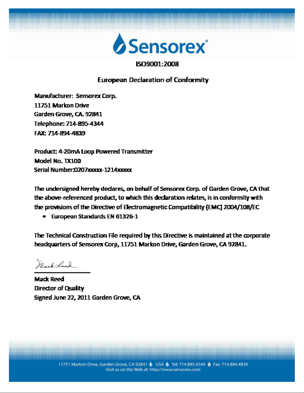
F 6/23/11 Added European Declaration of Conformity Certicate to inside cover
G 10/12/11 Correct ORP Range in Specications
H 01/2013 Updated product photo on cover.

PRODUCT INSTRUCTION MANUAL
1.1 General 1
1.2 Features 1
1.3 TX100 Specications 2
1.4 Quick Start Guide 3
2.1 Cord Grip Installation 5
2.2 Wall Mounting 6
2.3 Panel Mounting 7
2.4 DIN Rail Mounting 8
2.5 Pipe Mounting 9
3.1 General 10
4.1 General 11
4.2 Power 11
4.3 4-20mA Loop wiring 12
5.1 General 13
5.2 Direct Sensor Connection 13
6.1 Keypad Function 14
6.2 LCD Display 15
7.1 General 16
8.1 Getting Started 17
8.2 2-Point pH calibration 17
8.3 Temperature Calibration (with ATC) 19
Part 1 Introduction
Part 2 Transmitter Mounting
Part 3 Sensor Mounting
Part 4 Transmitter Electrical Installation
Part 5 Sensor Electrical Connection
Part 6 Keypad Function and LCD Display
Part 7 Transmitter Programming
Part 8 Calibration
Table of Contents

PRODUCT INSTRUCTION MANUAL
9.1 Probe Select Menu 20
9.2 Calibration Oset 21
9.3 Range Menu 22
9.4 Limit Menu 23
9.5 Hold Menu 24
9.6 Clean Probe Menu 25
9.7 Factory Reset 26
9.8 Manual Temperature Compensation (without ATC) 27
9.9 Temperature Unit Menu 28
10.1 General 29
10.2 Troubleshooting Guidelines 29
10.3 Troubleshooting Chart 29
11.1 Overview 30
11.2 Replacement Parts 30
12.1 Product Warranty 34
12.2 Return of Items 34
Part 10 Troubleshooting
Part 11 Maintenance
Part 9 Setup Functions
Part 12 Warranty and Product Returns
Table of Contents

Figure 2-1 Conduit port Knockout removal 5
Figure 2-2 Cord grip Mounting 5
Figure 2-3 Wall Mount 6
Figure 2-4 Panel Mount 7
Figure 2-5 DIN RAIL Mount 8
Figure 2-6 3/4” Pipe Mount 9
Figure 4-1 Power connections (schematic) 11
Figure 4-1a 4-20mA loop wiring (schematic) 12
Figure 5-1 Electrode connections (TBM1) 13
Figure 6-1 Transmitter Keypad 14
Figure 6-2 LCD Denition 15
Figure 7-1 Transmitter Main Menu 16
Figure 8-1 2-Point pH Calibration 18
Figure 8-2 Temperature Calibration 19
Figure 9-1 Probe Select Menu 20
Figure 9-2 Calibration Oset 21
Figure 9-3 Range Menu 22
Figure 9-4 Limit Menu 23
Figure 9-5 Hold Menu 24
Figure 9-6 Clean Probe Menu 25
Figure 9-7 Factory Reset Menu 26
Figure 9-8 Manual Temperature Compensation 27
Figure 9-9 Temperature Unit Menu 28
Figure 10-1 Troubleshooting Chart 29
Figure 11-1 Wall Mount Parts - Exploded View 30
Figure 11-2 Panel Mount Parts - Exploded View 31
Figure 11-3 DIIN- Rail Mount Parts - Exploded View 32
Figure 11-4 Pipe Mount Parts - Exploded View 33
Diagrams and Illustrations
PRODUCT INSTRUCTION MANUAL

PRODUCT INSTRUCTION MANUAL
Part 1 Introduction
1.1 General
The Model TX100 is a microprocessor-based, loop-powered monitoring system, designed for the continu-
ous measurement of pH, mV (ORP) and temperature. The full scale operating range of the transmitter may
be user adjusted to any value between 0-14 pH or -1999 to + 1999mV. All transmitter features are selectable
via the silicone keypad. Please read this manual thoroughly before operating the transmitter. For quick use,
please read the “Quick Start” Instructions supplied with your transmitter.
1.2 Features
- The TX100 is designed to be a fully isolated, loop powered pH/mV instrument for two-wire DC
applications.
- Can be user-adjusted for specic application span from 0-14pH or -1999mV to + 1999mV.
- Automatic temperature compensation via Pt1000 RTD.
- Instrument supplied in rugged NEMA 4X (IP65) enclosure.
- Built-in programmable sensor cleaning reminder.
- Probe select menu allows user to scale in pH or mV units.
- Calibration Oset menu allows user to calibrate transmitter to match another reference pH meter.
- Several preprogrammed pH buer selections available for calibration.
Page 1 of 35

PRODUCT INSTRUCTION MANUAL
Page 2 of 35
1.3 TX100 Specications
Measuring Range (pH) 0.00 to 14.00pH, 0.01 pH resolution,
+/- 0.01 accuracy
Measuring Range (ORP/mV) -1999mV to 1999mV, 1mV resolution,
+/- 2mV accuracy
Measuring Temperature Range -20 degC to 110 degC /-4 degF to 230degF,
0.1degC/F resolution
Current Output Range 2.00mA to 24mA (4-20mA galvanically isolated) , 0.01mA
resolution,+/-0.005mA accuracy
Enclosure NEMA 4X, IP65, ABS case with silicone keypad
HWD: 3.8” (96.52 mm) x 3.8” (96.52 mm) x 2.8” (71.5mm)
Weight approx. 1lb (.45kg)
Mounting Options Wall mount, panel mount, pipe mount and DIN rail (rail not
included)
Conduit Openings Standard: 2 - 3/8” openings cordgrips included.
Ambient Temperature Transmitter Service, 0 degC to 60 degC / 32 degF to 140 degF
Sensor Service – Refer to Sensor specications
Ambient Humidity 0 to 95% (non-condensing)
Location Designed for non-hazardous areas
Temperature Input 2-wire Pt1000 RTD with automatic compensation
Max. Sensor-to-Transmitter Distance 30 feet (9.1 meters)
Power 12-24 V .DC, 8 amp maximum current
EMI/RF EN 61326-1
Supply Voltage ( V DC) Max Resistance Load (Ohms)
12 150
16 350
20 550
24 750

PRODUCT INSTRUCTION MANUAL
Page 3 of 35
1.4 TX100 pH/MV Transmitter - QUICK START GUIDE
The TX100 is supplied with the following preset programming:
Factory Calibrated Values
pH Manual Oset = 0
mV Manual Oset = 0
Temperature Manual Oset = 0
Without TC, Default 25oC or 77oF
Range Mode [ - ] OFF
Range Mode Lo mV reset to -999 mV
Range Mode Hi mV reset to 999 mV
Range Mode Lo pH reset to 0.00
Range Mode Hi pH reset to 13.99
Hold Mode HLd Lr
Limit Mode O.r. OFF
Clean Probe Timer C.P. OFF
To change any of these parameters, please refer to the specic section in this manual (See Table of Contents).
a. Refer to Section 2 for installation instructions.
b. Connect electrode to transmitter as shown below.
c . Remove front cover from transmitter case by unscrewing four screws in rear corners of transmitter.
Connect a 12-24V DC, 8 amp maximum power supply as shown above. See page 6 for resistance load vs.
voltage.
d. Transmitter Programming/Setup

PRODUCT INSTRUCTION MANUAL
Page 4 of 35
e. If installed electrode is pH, move to step f.
If ORP/mV electrode is installed see Section 9.1 for Probe Selection programming.
f. Temperature Calibration is done at the factory before shipping. For temperature recalibration follow steps
shown in Section 9.8.
g. Factory preset temperature units are oC. To change to oF, follow instructions in Section 9.9.
h. For pH, perform Two-Point pH calibration as outlined in Section 8.2.
First buffer is pH 7.00 or 6.86 (NIST), second buffer choices are 4.01, 10.00 or 9.18 (NIST). A two-point
calibration must be performed. Three-point calibration is not necessary with the TX100.
Tabla de contenidos
Otros manuales de Transmisor de Sensorex

Sensorex
Sensorex TX2000 Manual de usuario

Sensorex
Sensorex CX100 Manual de usuario

Sensorex
Sensorex TX3000 Manual de usuario

Sensorex
Sensorex TX105 Manual de usuario

Sensorex
Sensorex TX2000 Manual de usuario

Sensorex
Sensorex TX2000 Manual de usuario

Sensorex
Sensorex TX3100 Manual de usuario

Sensorex
Sensorex CX105 Manual de usuario

Sensorex
Sensorex CT-1000 Manual de usuario
Manuales populares de Transmisor de otras marcas


Dejero
Dejero EnGo 3x Manual de usuario

Rosemount
Rosemount 4600 Manual de usuario

Speaka Professional
Speaka Professional 2342740 Manual de usuario

trubomat
trubomat GAB 1000 Manual de usuario

Teledyne Analytical Instruments
Teledyne Analytical Instruments LXT-380 Manual de usuario

Rondish
Rondish UT-11 Manual de usuario


