
Rivers Edge LANDMARK 600 BLIND Manual de usuario

GAS/OIL
RATIO
50:1
Operator's Manual
MODEL LM603
LANDMARK™
600 BLIND
Get parts online at
www.HuntRiversEdge.com
P/N: 39725
C/N: 40109
REV1: 1/26/22
© 2022 RETI
All Rights Reserved

Check for parts online at www.HuntRiversEdge.com or call 800-345-6007
2
Operator's Manual
Landmark™ 600 Blind
CONTENTS
Introduction/Warranty ..................................................................................................................................................................................................................2
Warnings/Tools Required .............................................................................................................................................................................................................3
Hardware Identication Chart....................................................................................................................................................................................................4
Assembly Instructions ............................................................................................................................................................................................................ 5-15
Notes................................................................................................................................................................................................................................................. 16
Illustrated Parts Breakdown................................................................................................................................................................................................16-19
Parts List........................................................................................................................................................................................................................................... 20
Notes...........................................................................................................................................................................................................................................21-23
INTRODUCTION
We appreciate your purchase of one of our world class products. Follow these few simple instructions and this product will
provide you many years of trouble-free pleasure. Instructions should be kept in a safe place and reviewed at least annually.
If for any reason you have a problem with your product, DO NOT return to the retailer, contact the Rivers Edge®customer
service department at 800-345-6007 for assistance.
WARRANTY
Ardisam, Inc., warrants this product under a one-year limited warranty to be free from defects in materials or workmanship or both for a period not
exceeding twelve consecutive months from the date of original purchase by the rst retail consumer or commercial end user. “Consumer use” means
personal recreational use by a retail consumer. “Commercial use”or “commercial application”means all other uses, including use for commercial, income
producing or rental purposes. Once a product has experienced commercial use, it shall thereafter be considered as a commercial use product for
purposes of this warranty. This warranty does not cover cracked windows, tent tears, or bent poles due to use in exteme weather conditions (i.e. hurricane
force winds) or uses other than those listed in the operator’s manual. Damage that occurs to a unit due to improper anchoring is not covered under
manufacturer warranty. This warranty applies to the original owner that provides a proof of purchase of the unit. The warranty is not transferable. The
warranty period begins on the date of purchase by the rst retail consumer or commercial end user, and continues for the twelve month consecutive
period thereafter. Any unit used in a commercial application is covered for a period of 90 days after purchase. For the warranty to be valid, the product
must be registered online at huntriversedge.com, within 30 days of purchase. Ardisam, Inc. shall not be obligated to ship any repair or replacement product
to any location outside of the United States of America or Canada.
This warranty applies only to products which have not been subjected to negligent use, misuse, uses other than those indicated in the product’s operator’s manual,
alteration, accident, use of unauthorized parts, failure to perform periodic maintenance as specied in product’s owner’s manual, or normal wear and tear.
There is no other expressed warranty. Implied warranties, including those of merchantability and tness for a particular purpose, are limited to one year from
purchase, or to the extent permitted by law. All other implied warranties are excluded. Liability for incidental or consequential damages are excluded to the extent
exclusion is permitted by law. Ardisam, Inc. does not assume, and does not authorize any other person to assume for us, any liability in connection with the sale
of our products. To obtain warranty service, you must have prior approval by calling our Customer Service Department at 1-800-345-6007. Ardisam, Inc. will at
no charge, repair or replace, at their discretion, any defective part which satises all conditions stated above. Ardisam, Inc. retains the right to change models,
specications and price without notice. Ardisam, Inc. shall not be obligated to ship any repair or replacement product to any location outside of the United States
of America or Canada.
If you choose to elevate this product to use above ground (on a tower type structure), only use Ardisam, Inc. original designed structures to do so. *Using manmade
structures or structures not manufactured by Ardisam, Inc. will void your warranty and waive any and all claims for liability against the manufacturer Ardisam,
Inc. If you choose to elevate this product on a Ardisam, Inc. brand tower structure, the warranty listed in the tower structure manual will apply to this product in
addition to the warranty statement in this operator’s manual.

Check for parts online at www.HuntRiversEdge.com or call 800-345-6007 3
Operator’s Manual
Landmark™ 600 Blind
WARNING
Read, understand and follow all assembly, inspection
and use instructions provided before each use. Failure to
follow warnings and instructions could result in serious
injury or death.
This product is for hunting purposes only! It is not to be
used as a camping tent or for any other function.
Never allow children to play in this product without adult
supervision. To do so could cause serious injury or death.
Never allow the material to cover your face. This material
can cause suocation and death if it is placed over face.
READ AND UNDERSTAND THE FOLLOWING WARNINGS BEFORE ASSEMBLY
STOP
WARNING
KEEP ALL FLAME AND HEAT SOURCES AWAY FROM
THIS TENT FABRIC. This tent meets the ammability
requirements of CPAI-84. The fabric may burn if left in
continuous contact with any ame source.The application
of any foreign substance to the tent fabric may render the
ame-resistant properties ineective.
WARNING
Only use approved RETI parts. Failure to do so may result
in serious injury or death!
TOOLS REQUIRED
- # 32563 7/16”WRENCHES 2
- - 1/2”WRENCH 1

Check for parts online at www.HuntRiversEdge.com or call 800-345-6007
4
Operator's Manual
Landmark™ 600 Blind
HARDWARE LIST
Item Part No. Description Image Qty
48 # 8909B BOLT
1/4 X 11/4 IN 8
49 # 48240B BOLT
1/4 X 11/2 IN 49
50 # 48153B BOLT
1/4 X 2 IN 4
51 # 48271B BOLT
1/4 X 21/4 IN 1
52 # 63282 BOLT
1/4 X 1 IN 1
53 # 15909 SPACER PLASTIC
6 MM 2
54 # 15908 SPACER PLASTIC
2.5 MM 1
55 # 30259 WASHER BLACK
PLASTIC 4 MM 3
56 # 48752B NUT 1/4 IN 63
57 # 60G5NYB NUT 5/16 IN 1
Check for parts online at www.HuntRiversEdge.com or call 800-345-6007 5
Operator’s Manual
Landmark™ 600 Blind
1
7
ASSEMBLY INSTRUCTIONS
IMPORTANT ASSEMBLY TIP:
Do not tighten any nut and bolt combinations completely
until instructions indicate to. Finger tighten plus one turn of
a wrench only! This will temporarily hold the lock- nut on the
bolt while helping alignment of all parts!
STEP 1
STEP 2
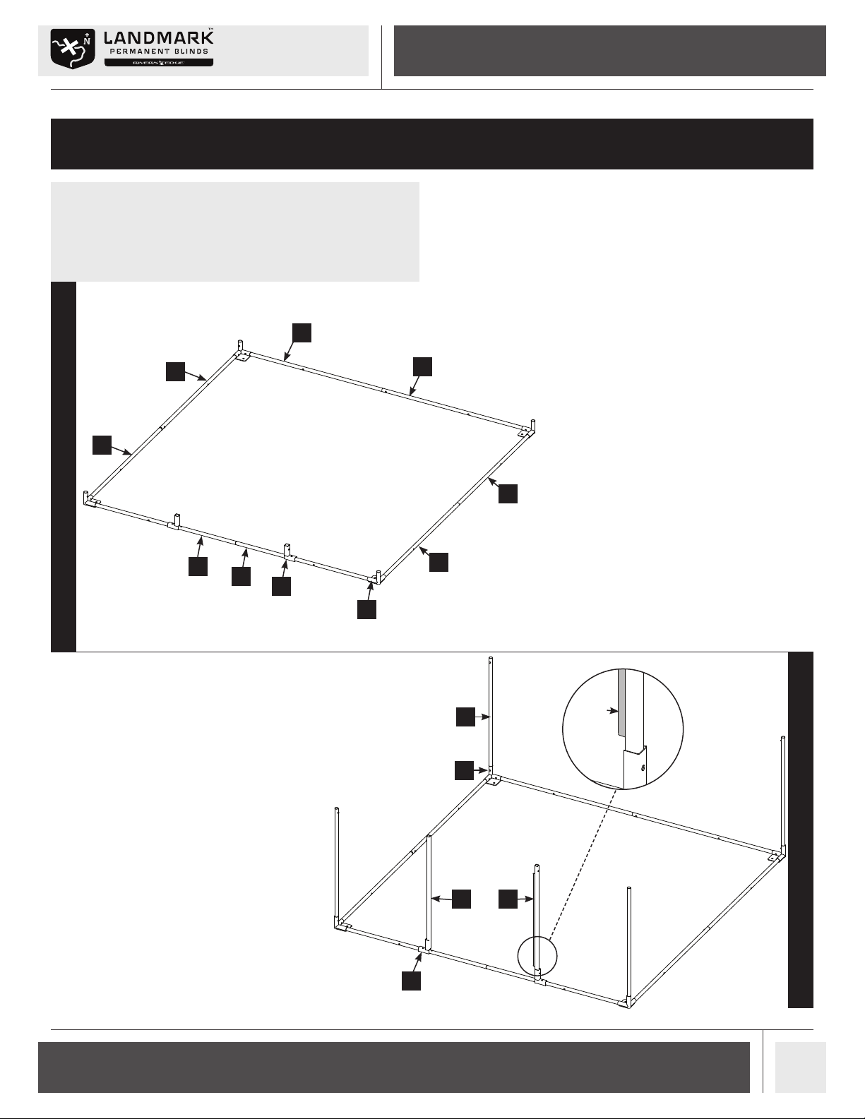
1. Open box, remove contents and organize all
parts together according to their labels. This
step greatly helps the ease of assembly.
Locate the four base hubs (1), three (6) poles,
three (7) poles, one (31) pole, one (32) pole
and two door hubs (9). SEE FIGURE 1.
Slide each (7) pole into the corresponding
(6) pole so that the snap button secures both
parts together. SEE FIGURE 1.
Slide the (32) pole into the corresponding
(31) pole so that the snap button secures
both parts together. SEE FIGURE 1.
Slide the two door hubs (9) down to the
second snap pin in assembled (31, 32) poles
as shown so that the snap buttons secure the
parts together. SEE FIGURE 1.
Slide the three assembled (6, 7) poles and
one assembled (31, 32) poles into the four
base hubs (1) so that the snap buttons secure
the parts together. You should now have the
bottom tier frame of the blind assembled.
SEE FIGURE 1.
2. Slide the four (18) poles into the base hubs
(1) so that the snap buttons secure the
parts together. SEE FIGURE 2.
Slide the (15) pole and (17) pole into the
door hubs (9) so that the snap buttons
secure the parts together. SEE FIGURE 2.
Be sure that the door stop plate on pole
(15) is facing interior of blind as shown in
DETAIL A.
7
6
9
32
31
6
6
7
DETAIL A
18
1
17
9
15
Door
stop plate
7
6
7
6
1
9
32
6
31
7
18
17
1
15
9
Check for parts online at www.HuntRiversEdge.com or call 800-345-6007
6
Operator's Manual
Landmark™ 600 Blind
18
2
17
15
30
23
24
56
49
22
23
24
23
24
56
49
STEP 3
STEP 4
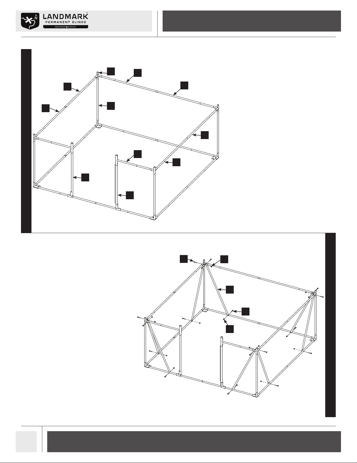
3. Attach the four middle hubs (2) to the (18)
poles so that the snap buttons secure the
parts together. SEE FIGURE 3.
Attach the two (30) parts to the middle hubs
(2) and the (15) and (17) poles as shown. The
end that attaches to the middle hub does not
attach with a snap button and will be secured
together with hardware in a later step. SEE
FIGURE 3.
Slide each (24) pole into the corresponding
(23) pole so that the snap button secures
both parts together. SEE FIGURE 3.
Slide the three assembled (23, 24) poles
into the four middle hubs (2). These do not
attach with snap buttons and will be secured
together with hardware in a later step. You
should now have the middle tier frame of the
blind assembled. SEE FIGURE 3.
4. Attach each of the eight (22) poles to the
bottom and middle tiers of the blind frame
using two 1/4-20 X 1-1/2 IN bolts (49) and
1/4-20 nuts (56). SEE FIGURE 4. Pay attention
to the orientation of the bolts! The head of
the bolt must be on the outside of the frame.
This helps prevent wear on the skin when fully
assembled.
STEP 5
224
18
23
24
23
17
30
24
23
15
49 56
22
49
56

Check for parts online at www.HuntRiversEdge.com or call 800-345-6007 7
Operator’s Manual
Landmark™ 600 Blind
STEP 6A
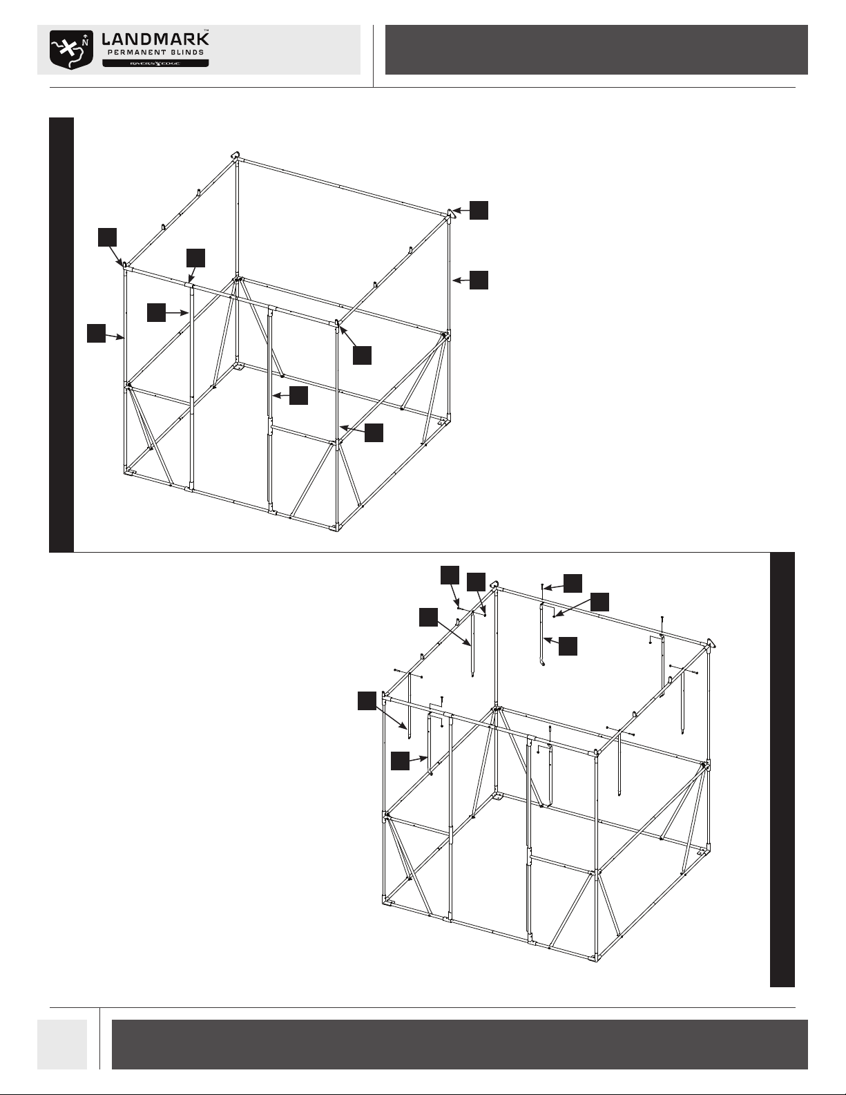
5. Slide the four (19) poles into the middle hubs
(2) so that the snap buttons secure the parts
together. Pay attention to the orientation
of the snap buttons. The snap buttons must
face each other as shown and each through-
hole must be located closer to the top. SEE
FIGURE 5.
Slide the (10) pole and (16) pole into the (30)
parts so that the snap buttons secure the
parts together. SEE FIGURE 5. Be sure that
the door stop plate on pole (16) is facing
interior of blind.
6. Slide the (7) pole into the (6) pole so that the
snap button secures the parts together. SEE
FIGURE 6A.
Slide a roof hub (3) onto each end of the
assembled (6, 7) poles so that the snap
buttons secure the parts together. SEE
FIGURE 6A.
Slide each (4) pole into each (5) pole so that
the snap button secures the parts together.
SEE FIGURE 6A.
Slide the assembled (4, 5) poles into the roof
hubs (3) so that the snap buttons secure the
parts together. SEE FIGURE 6A.
Slide the (34) pole into the (33) pole. Make
sure that the snap buttons on each pole
are facing the same direction and secure
together using one 1/4-20 X 1 IN bolt (52)
and 1/4-20 nut (56). SEE FIGURE 6A.
Slide the two door hubs (9) down to the
second snap pin in assembled (33, 34) poles
as shown so that the snap buttons secure the
parts together. SEE FIGURE 6A.
Slide the right and left front roof hubs (35, 36)
onto the assembled (33, 34) poles so that the
snap buttons secure the parts together. SEE
FIGURE 6A.
Slide the assembled (9, 33, 34, 35, 36) onto
the assembled (4,5) poles so that the snap
buttons secure the parts together. SEE
FIGURE 6A. You should now have the top tier
frame of the blind assembled.
STEP 5
STEP 5
10
30 16
19
2
Through hole
closer to top
3
6
7
9
52
4
36
4
5
5
35
33
56
34
10
16
30 2
19
5
4
36
7
3
34
6
956
33
5
52
4
35
Check for parts online at www.HuntRiversEdge.com or call 800-345-6007
8
Operator's Manual
Landmark™ 600 Blind
STEP 6B
STEP 7
6. Assemble the top tier frame of the blind
to the rest of the frame by lifting it up and
sliding the roof hubs (3) onto the rear (19)
poles, the right and left front roof hubs (35,
36) onto the front (19) poles, and the door
hubs (9) onto poles (10) and (16). Secure parts
together with the snap buttons. SEE FIGURE
6B.
7. Attach one end of the four angled brace (20)
poles and four angled brace (21) poles to the
top tier frame of the blind using a 1/4-20 X
1-1/2 IN bolt (49) and 1/4-20 nut (56) for each
brace. Let them hang for now as shown. SEE
FIGURE 7.
19
3
35
36
19
19
9
16
10
20
56 49
21
49
56
20
21
9
36
19
16
35
19
3
10
19
21
56
49
21
20
20
49 56

Check for parts online at www.HuntRiversEdge.com or call 800-345-6007 9
Operator’s Manual
Landmark™ 600 Blind
21
56
19
49
20
STEP 8
STEP 9
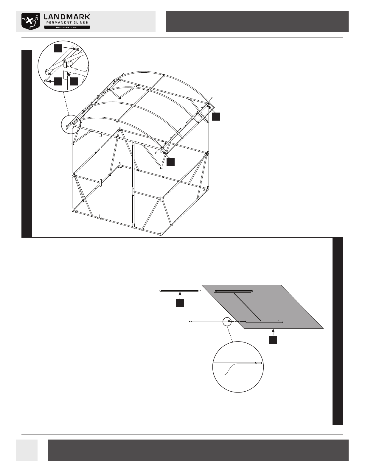
8. Attach each set of angled braces (20, 21) to
the four (19) poles using a 1/4-20 X 1-1/2 IN
bolt (49) and 1/4-20 nut (56) for each set. SEE
FIGURE 8.
9. Slide the four (26) poles into the four (27)
poles and set aside. SEE FIGURE 9.
Slide the three (8) poles into the three (25)
poles so that the snap buttons secure the
parts together and set aside. SEE FIGURE 9.
Attach the assembled (26, 27) poles in the
center to one assembled (8, 25) pole using
four 1/4-20 X 2 IN bolts (50) and 1/4-20 nuts
(56). SEE FIGURE 9.
Attach the remaining two assembled (8, 25)
poles to the ends of assembled (26, 27) poles
using eight 1/4-20 X 1-1/4 IN bolts (48) and
1/4-20 nuts (56). SEE FIGURE 9. Pay attention
to the orientation of the bolts! The head of
the bolt must be on the top of the roof frame.
This helps prevent wear on the skin when
fully assembled. Securely tighten all loose roof
hardware at this time.
26 50
27
25
856
48
56
19
56
21
49
20
26 50
56
27
48
56
8
25
Check for parts online at www.HuntRiversEdge.com or call 800-345-6007
10
Operator's Manual
Landmark™ 600 Blind
DETAIL B
49
56
DETAIL C
36
STEP 10
STEP 11
10.Attach the assembled roof to the rest of the
blind frame using eight 1/4-20 X 1-1/2 IN
bolts (49) and 1/4-20 nuts (56). SEE FIGURE
10. Pay attention to the orientation of the
roof! The roof attaches on the inside of the
roof hub (3, 35, 36) tabs. SEE DETAIL B.
Securely tighten all loose hardware at this time.
11.It is now time to begin the attachment of the
sewn panels to the frame. Lay out all sewn
panels and familiarize yourself with them. Pay
special attention to the back wall panel and
the two side wall panels as they look similar
at rst glance but are dierent. You can
identify the panels by sewn tags on the inside
near the window.
While paying attention to the orientation,
SEE DETAIL C, slide the four (28) window
poles into the sewn sleeves on the two side
wall panels (42) as shown, two poles per
panel. SEE FIGURE 11.
49 36
56
42
28
35
28
3
28
Este manual sirve para los siguientes modelos
1
Tabla de contenidos


