
OptoSigma JC-01 Manual de usuario

Jog Controller
JC-01
Instruction manual
MJ-1026-01.01


i
This time thank you for having you purchase a Jog controller.
■About this instruction manual
This instruction manual describes the correct usage and functions of the equipment and notes on
use. Please read carefully before use to ensure proper operation. Also, keep this manual in a handy
place for when you do not understand when using it.
The content of the instruction manual has been prepared with all possible measures. If there are any
suspicious points, errors or omissions, please contact us or your distributor.
* Reprinting and copying of the instruction manual requires our consent.
* The contents of the instruction manual and product specifications are subject to change without
notice.
■Warranty
If a failure occurs due to our manufacturing or delivery within one year from the date of purchase,
we will repair it free of charge.
However, in the following cases, repair will be charged even if it is within one year of purchase.
1. If there is a failure or damage due to usage or carelessness different from what is described
in the instruction manual
2. If there is a malfunction or damage due to improper modification, adjustment or repair
3. If there is a failure or damage due to natural disaster, fire, or other external factors
■Repair
We will repair it. If you suspect a malfunction or damage, please contact us or your distributor.
When transporting this equipment to us, pack it carefully so that it will not be damaged during
transportation, and write down the occurrence, failure or damage. In addition, we cannot guarantee
about malfunction and damage caused by transportation.
■Contact
Tokyo Head Office TEL +81-3-5638-6551
Osaka Branch TEL +81-6-6307-4835
Kyushu Sales Office TEL +81-92-481-4300
ii
■Precautions for use
Please read this instruction manual carefully before use to ensure correct use. Then save it carefully
and read it when necessary.。
• This device is used to operate the following Yaskawa stage controller at hand. Do not use for any
other purpose.
Model
FC-411 FC-414 FC-511 FC-514 FC-611
FC-911
• This instrument is a precision instrument. Please handle with care.
• Make sure that there is no impact or excessive force on the equipment.
• Maintain the installation environment described in this instruction manual.
• If the equipment is used in a manner not specified in this manual, the protection functions of the
equipment may be impaired. The Company is not liable for any damages arising from use that
violates this precaution.
• Fire caused by this equipment, damage caused by extinguishing agents, earthquakes, flooding,
lightning strikes, other accidents, intentional or negligence of customers and third parties, use
other than the intended use of the product, use in environments other than specifications The
Company is not liable for any damages.
• The Company assumes no responsibility whatsoever for any damage to human life or property
caused by a failure or malfunction caused by connecting this equipment to equipment or
equipment other than our stage controller.
• No warranty other than those described in this instruction manual.
■ Safety Please be sure to observe
Explains what you must observe to prevent harm to people and others, and damage to property.
• The degree of harm or damage caused by improper use is classified and explained in the following
display.
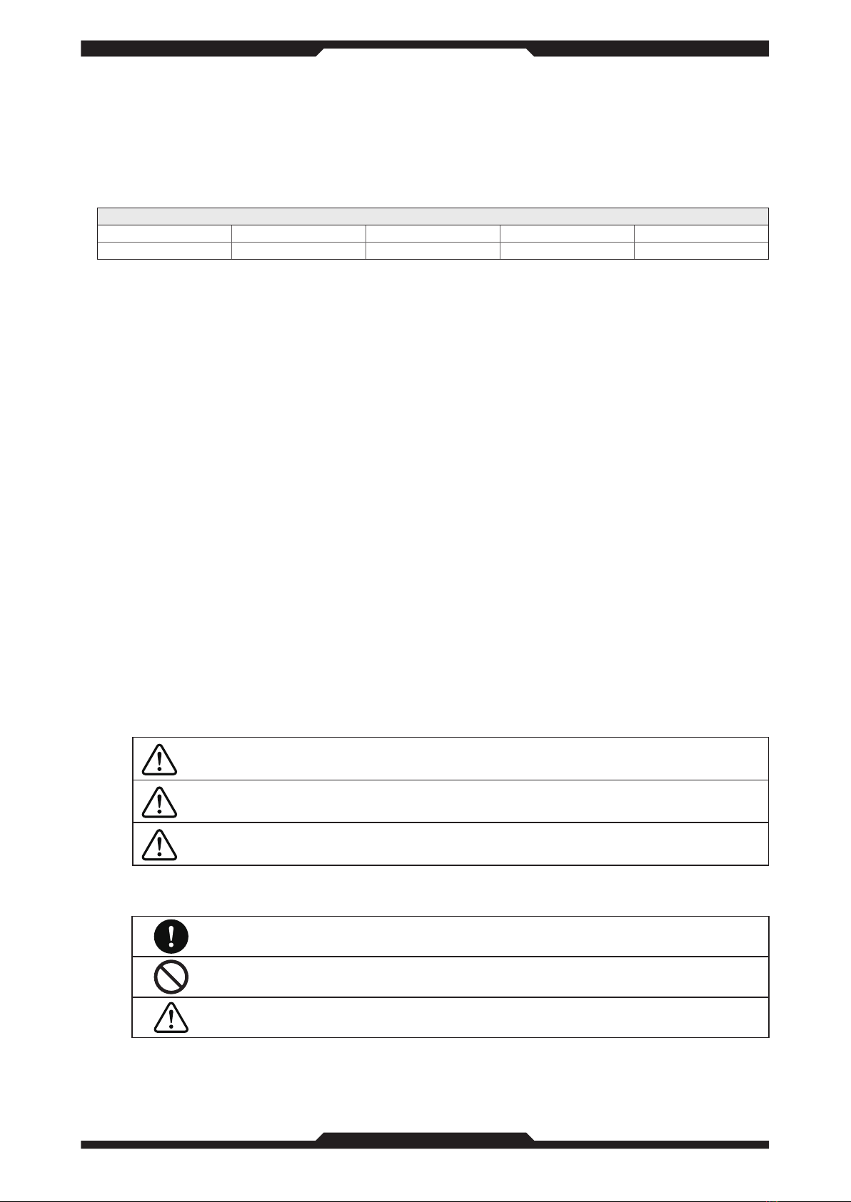
DANGER
The column of this display is“It is assumed that the risk of death or
seriousness is imminent.”
WARNING
The column of this display is the content“It is assumed that there is a
possibility of death or serious injury”.
CAUTION
The column of this display is the content“It is assumed that there is a
possibility of causing damage or physical damage only”.
• The types of content to be protected are categorized and explained by the following indications.
Indicates "forced" content that must be executed.
Indicates "prohibited" contents that must not be executed.
Indicates the“Caution”that you should be aware of. Also displayed on the equipment.

iii
• Explains what you should follow.
WARNING
Do not use in an explosive atmosphere. Never use it in a place where flammable or
explosive gas or vapor is present because it may cause an explosion or fire.
Do not place in a corrosive atmosphere. Doing so may cause corrosion of the
conductor or poor contact of the connector, which may cause malfunction or failure,
resulting in a fire.
Do not use the product in a broken or damaged state.
There is a risk of electric shock, smoke, or fire. Unplug the power cable from the outlet.
Do not use the product where it will be exposed to water. It may cause an electric
shock or malfunction.
Do not open the cover. It may cause an electric shock or malfunction.
Do not connect other than our stage controller described in this instruction manual.
Doing so may cause a failure of this instrument and connected equipment.
■Precautions for install
The following are precautions for installing this equipment. Please be sure to observe.
• Avoid places where the temperature and humidity are high, where the product is exposed to
direct sunlight, or where the temperature changes rapidly.
• Do not install it in a place where it will be exposed to water.
• Ensure that the ambient temperature of this equipment does not exceed 40 ℃ .
• Do not use the product in a place where there is a strong magnetic field or electric field, or where
there is a lot of distortion or noise in the input power supply waveform.
■Cleaning
If it gets dirty, use a soft cloth with a mild detergent diluted with water and wipe gently.
WARNING
When cleaning, be sure to remove it from the stage controller.
CAUTION
Use only neutral detergent diluted with water. Discoloration and roughness of the painted surface,
fading of printed characters, and cloudiness of the acrylic board may occur.

iv
Contents
■About this instruction manual i
■Warranty i
■Repair i
■Contact i
■Precautions for use ii
■ Safety Please be sure to observe ii
■Precautions for install iii
■Cleaning iii
1. Overview 1
2. Package Contents 1
3. Part names and functions 1
3-1.Panel 1
3-2.Cable 6
4. Specification 7
4-1. Basic specifications 7
4-2. General specifications 7
5. Dimensions 8
6. Trouble shooting 9
7. Update history 10
8. Index 12

v

1
1 2 3 4 5 6 7
1. Overview
This equipment is used to operate our stage controller at hand. By pressing each button, stage
operation, teaching operation, emergency stop, mode switching, and sleep execution can be
performed. The controllers that can be connected are shown below.
Model
FC-411 FC-414 FC-511 FC-514 FC-611
FC-911
2. Package Contents
Purchasers should find that the package contains the items listed below. If anything is missing or
damaged, contact us or your distributor.
Name Model or specification Quantity Remarks
Jog Controller JC-01 1
Instruction manual - 1 This book
3. Part names and functions
3-1.Panel
EMERGENCY
Zero 2
Remote
Teach
Long push
Mode
Local
StopStart/Pause
Teach
Select
EOrg 2EOrg 1
Org 2Org 1 Zero 1
One Step
Cancel
Busy
Error
Disconnect
Lock
Jog ControllerJC-01
Sleep
to unlock
Long push
to execute
Long push
2
1
1
3
421 3
10
1000
100
Long push
5OffOn

2
1 2 3 4 5 6 7
(1) Display unit
Jog ControllerJC-01
The display shows the positioning status, axis name, coordinate value, unit, and error. The error
is displayed on the axis where the error has occurred, and all the errors that have occurred are
displayed at regular intervals. For the positioning status, axis names, units, and errors, see the
instruction manual for the stage controller.
123
X 0 . 0 0 0 0 m
Y0 . 0 0 0 0 m
4
• Display contents
No Item Contents
1 Axis name The upper side is the first axis side (X), and the lower side is the second axis
side (Y). Depends on the stage controller setting.
2 Coordinate value The upper side is the first axis side, and the lower side is the second axis side.
3 Unit
The upper side is the first axis side, and the lower side is the second axis side.
Depends on the stage controller setting.
• For nanometers, it is "n".
• For micrometer, it is "u".
• For millimeters, it is "m".
• In the case of degrees, it is "° ".
• When there is no display, the display is such that the smallest digit of the
coordinate value is the digit of the resolution of the connected stage
controller. For details, see the instruction manual for the stage controller.
4Positioning status
READY Positioning is completed and stays within the in-position
range.
READY It is out of the in-position range after positioning is
completed.
BUSY The positioning operation is in progress.
+BUSY It is operating in the plus direction during Jog key operation.
-BUSY Operating in the minus direction during Jog key operation.
no display BUSY Command operation (other than Jog key operation) or
error is occurring.
The keys that can be used depending on the positioning status, errors and modes are shown
below.
Mode
Error
Positioning status
Local, Remote Teach
Org 2Org 1
Zero 2Zero 1
EOrg 2EOrg 1
Disconnect
Long push
Lock
to unlock
Long push
Sleep
to execute
Long push
Long push
Mode
Long push
Mode
One Step
Stop
Start/Pause
Teach
Select
Disconnect
Long push
Lock
to unlock
Long push
Sleep
to execute
Long push
Cancel
Busy
Error Cancel
Busy
Error
+
--
-
None
Limit error
Emergency stop
Overflow error Cancel
Busy
Error Cancel
Busy
Error
Other error - -

3
1 2 3 4 5 6 7
(2) EMERGENCY switch(Local, Remote, Teach)
EMERGENCY
OffOn
Emergency stop switch. Used to stop the stage operation urgently. Can be used in all modes.
When the power is supplied to the instrument, pressing the switch locks the instrument to the
On side, turns on the lamp in the button, and causes an emergency stop. To cancel, press the
switch again to turn it off, and press the Busy Error Cancel key. The EMERGENCY switch can
be used even if power is not supplied to this instrument as long as it is connected to our stage
controller. In this case, the lamp does not turn on even if the switch is pressed to the On side
and an emergency stop is performed. To release from this state, perform the above release
operation after reconnecting this equipment and supplying power, or cancel the busy error from
the stage controller. For details, see the instruction manual for the stage controller.
(3) Mode key(Local, Remote, Teach)
Remote
Teach
Long push
Mode
Local
The mode switches each time the mode of the stage controller is pressed and held. The keys
that can be used in each mode are different. See "Display" for details.
(4) Org1, Org2 key(Local, Remote) Org 2Org 1
Return the stage to the mechanical origin. Org1 is the first axis and Org2 is the second axis.
During execution, the green lamp lights. One axis can be executed while the other axis is being
executed. Press again during execution to stop the stage. The mechanical origin mode and
operation speed depend on the setting of the stage controller. For details, see the instruction
manual for the stage controller.
(5) EOrg1, EOrg2 key(Local, Remote) EOrg 2EOrg 1
Return the stage to the coordinate zero position (electric home return). EOrg1 is the first
axis and EOrg2 is the second axis. The green lamp lights during execution. One axis can be
executed while the other axis is being executed. Press again during execution to stop the
stage. The operating speed depends on the setting of the stage controller. For details, see the
instruction manual for the stage controller.
Este manual sirve para los siguientes modelos
6
Tabla de contenidos
Otros manuales de Controladores de OptoSigma

OptoSigma
OptoSigma GSC-02A Manual de usuario

OptoSigma
OptoSigma JD-101 Manual de usuario

OptoSigma
OptoSigma GSC-01 Manual de usuario

OptoSigma
OptoSigma SRC-101 Manual de usuario

OptoSigma
OptoSigma SHOT-102 Manual de usuario

OptoSigma
OptoSigma CJ-200A Manual de usuario

OptoSigma
OptoSigma GSC-02 Manual de usuario


