Optica D224M Manual de usuario

Optica HD Indoor Dome Network Camera
Model: D224M
User’s Manual
Ver. 1.3

1
Table of Contents
1. Overview.................................................................................................................................. 2
1.1 Features ........................................................................................................................ 2
1.2 Package Contents ......................................................................................................... 3
1.3 Dimensions.................................................................................................................... 4
1.4 Connectors .................................................................................................................... 5
2. Camera Cabling....................................................................................................................... 6
2.1 Connect Power.............................................................................................................. 6
2.2 Connect Ethernet Cable ................................................................................................ 6
2.3 Connect Alarm I/O......................................................................................................... 6
3. System Requirements ............................................................................................................ 7
4. Access Camera....................................................................................................................... 8
5. Setup Video Resolution........................................................................................................ 12
6. Configuration Files Export / Import..................................................................................... 13
Appendix A: Technical Specifications........................................................................................ 14
Appendix B: Delete the Existing Optica Viewer......................................................................... 16
Appendix C: Setup Internet Security .......................................................................................... 17
Appendix D: Video Resolution .................................................................................................... 18
D224M - Quad Streams .......................................................................................................... 18
D224M - Triple Streams.......................................................................................................... 22
D224M - Dual Streams ........................................................................................................... 25
D224M - Single Stream........................................................................................................... 26

2
1. Overview
The D224M HD Indoor Dome Network Camera is an easy setup camera with
PoE supported to reduce complicate cabling. Up to 1080P Megapixel
Resolution is offered for providing high definition images. Quad Streams
Compression (H.264 Baseline / Main / High Profile + MJPEG) are supported for
efficient bandwidth and storage management. For dark environments, the
camera has incorporated WDR, 3DNR and Day/Night ICR technologies to
capture clear images in lowlight conditions.
1.1 Features
•Progressive Scan CMOS Sensor
•1080P Resolution
•Dual Streaming- Full HD 1080P Real Time + D1 Real Time
•Quad Streams Compression- H.264 Baseline / Main / High Profile + MJPEG
•Multi-language Support
•Tampering Alarm
•Wide Dynamic Range
•Motion Detection
•Privacy Masks
•Smart Picture Quality / 3D Noise Reduction
•Vertical View Mode (image rotation by 90 degrees)
•Smart IR Mode
•Network Failure Detection
•True Day/Night (ICR)
•IR LED Module (working distance up to 25m)
•microSD Support
•ONVIF Support

3
1.2 Package Contents
Please check the package contains the following items listed below.
D224M HD Dome Camera
D224M
HD Dome Camera
Power Terminal Block
Self Tapping Screws (x3)
Plastic Screw Anchors (x3)
Quick Start Guide
CD
(bundled software and documentation)

4
1.3 Dimensions
The dimensions of the IP Camera are shown below.
D224M

5
1.4 Connectors (Indoor Only)
The diagram below shows the IP Camera’s reset button and various connectors.
Definition for each connector will be given as follows.
No. Connector Pin Definition Remarks
1 RJ-45 - 10/100 Mbps Ethernet / PoE
2 Power
(AC 24V / DC 12V)
1 AC 24V: Power-1 DC 12V: Power Power
connection
2 AC 24V: GND DC 12V: Reserved
3 AC 24V: Power-2 DC 12V: GND
3 microSD Card Slot - For video recording storage
4 -- - --
5 Alarm & Audio I/O
1 Alarm In (–)
Alarm
connection
2 Alarm In (+)
3 Alarm Out (–)
4 Alarm Out (+)
5 Audio Out (L) Line Out
6 Audio Out (R)
7 GND
8 Audio In Line In
6 Default Button - Press the button for at least 20 seconds with one
finger to restore the system.
NOTE: Insert the SD card into the microSD card slot before powering on
the camera. If the camera is already powered on, reboot the camera
after the SD card is inserted.

6
2. Camera Cabling
Please follow the instructions below to complete IP Camera connection.
2.1 Connect Power
For power connection, please refer to section Connectors. Alternatively, users
can power the camera by PoE. Refer to the section below to connect the
Ethernet Cable for PoE connection.
NOTE: If PoE is used, make sure Power Sourcing Equipment (PSE) is
in used in the network.
2.2 Connect Ethernet Cable
Use of Category 5 Ethernet Cable is recommended for network / PoE
connection. For best transmission quality, cable length shall not exceed 100
meters. Connect one end of the Ethernet Cable to the RJ-45 connector of the IP
Camera / Function Cable, and plug the other end of the cable to the network
switch or PC.
NOTE: In some cases, Ethernet Crossover Cable might be needed
when connecting the IP Camera directly to the PC.
Check the status of the link indicator and activity indicator LEDs. If the LEDs are
unlit, please check the LAN connection.
Green Link Light indicates good network connection.
Orange Activity Light flashes for network activity indication.
2.3 Connect Alarm I/O
For Indoor models, there is an 8 pins terminal block for the Alarm I/O and the
Audio I/O connections. For Outdoor models, the Alarm I/O is connected by a
4 pins terminal block. Refer to sections Connectors for the pin definitions.

7
3. System Requirements
To perform the IP Camera via web browser, please ensure the PC is in good
network connection, and meet system requirements as described below.
Items System Requirement
Personal Computer
1. Intel®Pentium®M, 2.16 GHz or
Intel®CoreTM2 Duo, 2.0 GHz
2. 2 GB RAM or more
Operating System Windows VISTA / Windows XP / Windows 7
Web Browser Microsoft Internet Explorer 6.0 or later
Firefox
Chrome
Safari
Network Card 10Base-T (10 Mbps) or 100Base-TX (100 Mbps) operation
Viewer ActiveX control plug-in for Microsoft IE
8
4. Access Camera
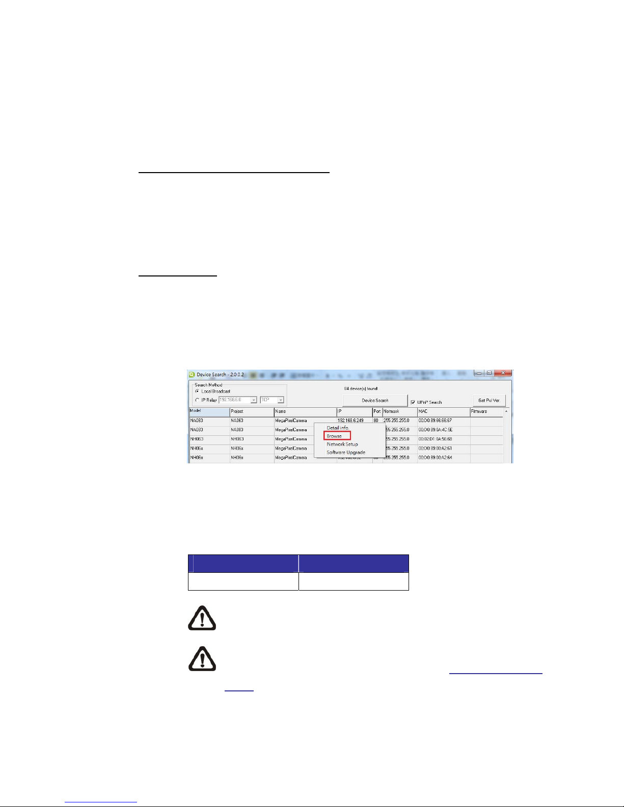
For initial access to the IP Camera, users can search the camera through the
installer program: DeviceSearch.exe, which can be found in “DeviceSearch”
folder in the supplied CD.
Accessing Device Search Software
Step 1: Double click on the program Device Search.exe. After its window
appears, click on the <Device Search> button on the top side.
Step 2: The security alert window will pop up. Click on <Unblock> to continue.
Device Search
Step 3: Click on <Device Search> again, and all the finding IP devices will be
listed in the page. The IP Camera default IP setting is DHCP.
Step 4: Double click or right click and select <Browse> to access the camera
directly via web browser.
Step 5: A prompt window requesting for default username and password will
appear. Enter the default username and password shown below to
login to the IP Camera.
Login ID Password
Admin 1234
NOTE: ID and password are case sensitive.
NOTE: It is strongly advised that administrator’s password be
altered for the security concerns. Refer to Camera Firmware
Menu for further details.

9
Additionally, users can change the network property of the IP Camera to DHCP
or Static IP directly in the device finding list. Refer to the following section for
changing the IP Camera’s network property.
Example of Changing IP Camera’s Network Property
Step 1: In the finding device list, click on the IP Camera that is wished to
change its network property. On the selected item, right click and
select <Network Setup>. Meanwhile, record the IP Camera’s MAC
address, for future identification.
Step 2: The Network Setup page will come out. Select <DHCP>, and click
<Apply> button down the page.
Step 3: Click on <OK> on the Note of setting change. Wait for one minute to
re-search the IP Camera.
Step 4: Click on the <Device Search> button to re-search all the devices.
Then select the IP Camera with the correct MAC address.
Double click on the IP Camera, and the login window will come out.
Step 5: Enter Username and Password to access the IP Camera.
Installing Optica Viewer Software Online
For the initial access to the IP Camera, a client program, Optica Viewer, will be
automatically installed to the PC when connecting to the IP Camera.
If the Web browser doesn’t allow Optica Viewer installation, please check the
Internet security settings or ActiveX controls and plug-ins settings (refer to
chapter Appendix C: Setup Internet Security) to continue the process.
The Information Bar (just below the URL bar) may come out and ask for
permission to install the ActiveX Control for displaying video in browser.
Right click on the Information Bar and select <Install ActiveX Control…> to allow
the installation.
Otros manuales para D224M
1
Tabla de contenidos
Otros manuales de Cámara de seguridad de Optica

Optica
Optica D204M Manual de usuario

Optica
Optica D104; D204M Manual de usuario

Optica
Optica D122 Manual de usuario

Optica
Optica B102 Manual de usuario

Optica
Optica P218Z Manual de usuario

Optica
Optica DV104 Manual de usuario

Optica
Optica D122 Manual de usuario

Optica
Optica P218Z Manual de usuario

Optica
Optica D122 Manual de usuario

Optica
Optica D122 Manual de usuario


