NOVAK ESC PROFILE SOFTWARE Manual de usuario

NOVAK ELECTRONICS • PROFILE SOFTWARE 1
Introduction .....................................................................................2
What’s Included ...............................................................................2
Adjustable Parameters.....................................................................3
Hardware Installation ....................................................................11
Operating System Requirements ..................................................12
Running From 3.5” Floppy Drive...................................................12
Installing/Running Software .........................................................13
Windows 3.1® & Windows 95® ....................................................13
MS® DOS .......................................................................................13
Precautions ....................................................................................14
Acquiring Default Parameters .......................................................14
Uploading Parameters From Cyclone ...........................................15
Editing Parameters ........................................................................16
Downloading Parameters To Cyclone ...........................................18
Saving Parameters To Disk ............................................................19
Reading Parameters From Disk .....................................................19
Monitoring Transmitter Trigger....................................................20
Sample Profile Data .......................................................................20
Service Procedures ........................................................................21
Service Return Sheet .....................................................................22
Trouble-Shooting Guide ................................................................23
Software License & Product Warranty ..........................................23
Profiles ...........................................................................................24
Profiles ...........................................................................................25
Index ..............................................................................................26
Notes..............................................................................................28
Complete Instruction Manual for
the Novak ESC Profile Software
Program.
CONTENTS

NOVAK ELECTRONICS • PROFILE SOFTWARE 2
INTRODUCTION
When designing an electronic speed control, the Novak engineers
are put to the task of setting design parameters such as how wide
the Deadband should be, what percentage of Full Drive should be
applied with the first pulse of transmitter information, or what
Brake and Drive Frequencies to use. In the past our engineers would
determine the best possible compromise for these parameters
based on different vehicles and driving styles. While these fixed
designs were perfect for some applications and some drivers, they
were not right for others. It became clear that a speed control was
needed that allowed the driver to modify several of the design
parameters to fit their differing applications and needs.
During testing, our engineers found that different vehicles required
different parameter values, just as each individual driver required
different parameters to obtain the type of feel that they desired.
With this criteria in mind, Novak proudly brings you the Cyclone
Programmable Speed Control and the Profile Software (#1030).
WHAT’S INCLUDED
• PROFILE SOFTWARE
Specialized profiling software that allows you to customize the
adjustable parameters of the Novak Cyclone Electronic Speed
Control (ESC), including the Deadband width, Minimum Drive
percentage, Drive & Brake PWM Frequencies, and more.
• DATALINK HARDWARE
Comes with everything needed to hook-up your Cyclone speed
control to an IBM®-compatible personal computer. Including
DataLink for connecting to speed control, DB9/RJ11 adaptor
for connecting to the communications serial port of computer,
and an RJ11 (6-conductor) cable for connecting the DataLink
to the DB9/RJ11 adaptor.
• ELECTRONIC INSTRUCTION MANUAL
Complete instruction manual is included on disk as a PDF file.

NOVAK ELECTRONICS • PROFILE SOFTWARE 3
ADJUSTABLE PARAMETERS
Novak’s Profile Software allows you to access the Cyclone speed
control’s previously hidden fourth Profile. This user-programmable
Profile gives you the ability to customize several of the design
parameters of the speed control. This adjustability will allow you
to custom tailor the speed control’s response and feel to your
preference for different applications. This section lists the user-
adjustable parameters, their descriptions, and applications:
• NEUTRAL
–Measured in microseconds (µs).
–Position at which the speed control is at rest, with no Drive or
Brake being applied.
–Initial value is taken from the transmitter, as recorded in the One-
Touch Set-Up memory of the speed control.
• FULL THROTTLE
–Measured in microseconds (µs).
–Trigger position at which speed control reaches Full Drive.
–Initial value is taken from the transmitter, as recorded in the One-
Touch Set-Up memory of the speed control.
• FULL BRAKE
–Measured in microseconds (µs).
–Trigger position at which speed control reaches Full Brake.
–Initial value is taken from the transmitter, as recorded in the One-
Touch Set-Up memory of the speed control.
Note: For optimum performance from your Cyclone, the values for Full Throttle
and Full Brake should be at least 350µs.
Figure 1: Neutral, Full Throttle, and Full Brake shown graphically by percent of
drive or brake applied at a given trigger position.
DEADBAND
TRIGGER POSITION
Neutral
Full
Brake Full
Throttle
10 10
20
50
100
20
50
100
% FULL DRIVE
% FULL BRAKE

NOVAK ELECTRONICS • PROFILE SOFTWARE 4
ADJUSTABLE PARAMETERS (CONT.)
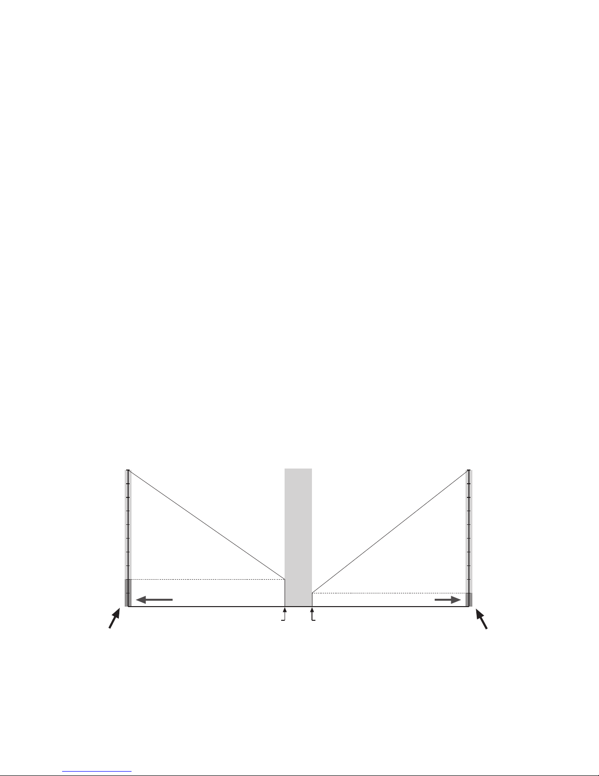
• DEADBAND
–Measured as percentage (%) of Full Throttle trigger position.
–Space between Minimum Brake and Minimum Drive, with
Neutral located at the center of this space (Figure 2).
–Changing the Deadband value will change the point at which
forward Drive begins with respect to Neutral.
–Increasing Deadband will require more trigger movement away
from Neutral to reach both the first pulse of Drive and the first
pulse of Brake. Example: Adding 10% to the value of Deadband
will in turn add 5% Deadband in the Full Throttle trigger
direction, and 5% Deadband in the Full Brake trigger direction.
–Decreasing Deadband will require less trigger movement to
reach the first pulses of Drive and Brake.
Figure 2: Deadband graphically displayed as a percentage of the Full Throttle
trigger position, which is measured in microseconds.
DEADBAND
18%
TRIGGER POSITION
Neutral Full
Throttle
10 10
20
50
100
20
50
100
100%18%
% FULL DRIVE
% FULL BRAKE
Minimum
Drive
Minimum
Brake

NOVAK ELECTRONICS • PROFILE SOFTWARE 5
• DRIVE PWM FREQUENCY
–Measured in Hertz (Hz).
–Frequency at which the duty cycle information is being sent
from speed control to motor (How many times per second the
motor is being cycled on and off to control it’s speed).
–Drive PWM Frequency controls acceleration characteristics of
your vehicle with respect to trigger movement in the Full
Throttle direction (Figure 3). By changing the value of Drive
PWM Frequency you change the manner in which the vehicle
responds to transmitter trigger input.
–Increasing Drive PWM Frequency requires more initial trigger
movement to obtain the same given speed. Light
vehicles feel
more controllable / Heavy vehicles more sluggish.
–Decreasing Drive PWM Frequency requires less initial trigger
movement to obtain the same given speed. Light vehicles are
harder to control at the low end (possibly spinning the rear
wheels) / Heavy vehicles are more reactive.
–
This parameter can be used as a valuable tuning asset for
different types of motors and track conditions.
ADJUSTABLE PARAMETERS (CONT.)
Figure 3: Graphical location of area affected by Drive PWM Frequency.
DEADBAND
TRIGGER POSITION
Neutral
Full
Brake Full
Throttle
10 10
20
50
100
20
50
100
DRIVE PWM
FREQUENCY
% FULL DRIVE
% FULL BRAKE

NOVAK ELECTRONICS • PROFILE SOFTWARE 6
• MINIMUM DRIVE
–Measured as percentage (%) of the Full Drive value.
–Amount of Drive applied with the first pulse of transmitter
throttle information (Figure 4).
–Increasing the Minimum Drive will make the speed control
begin at a greater percentage of Full Drive. This is useful for
tracks with good traction and for heavier vehicles to eliminate
‘dead’ trigger movement before the motor can actually move
the vehicle (and will increase the vehicle’s minimum rolling speed).
–Decreasing the Minimum Drive will make the speed control
start at a smaller percentage of Full Drive. This is useful for
tracks with low-bite and lighter vehicles where lower initial
power will give more controllability. This parameter is also a
valuable tuning asset for different types of motors.
ADJUSTABLE PARAMETERS (CONT.)
Figure 4: Graphical representation of Minimum Drive and Minimum Brake as
percentage of Full Drive and Full Brake, respectively.
DEADBAND
TRIGGER POSITION
Minimum
Drive
[10%]
Minimum
Brake
[20%]
10 10
20
50
100
20
50
100
256 DISCRETE BRAKE STEPS
256 DISCRETE FORWARD STEPS
% FULL DRIVE
% FULL BRAKE

NOVAK ELECTRONICS • PROFILE SOFTWARE 7
• BRAKE PWM FREQUENCY
–Measured in Hertz (Hz).
–Frequency at which the duty cycle information is being sent
from speed control to motor for braking.
–Brake PWM Frequency controls deceleration characteristics of
your vehicle with respect to trigger movement in the Full Brake
direction (Figure 5). Changing Brake PWM Frequency allows
you to change the manner in which the vehicle responds to
brake trigger input.
–Increasing the Brake PWM Frequency will require more initial
trigger movement to obtain the same amount of braking. Light
vehicles brake more controllably under initial braking / Heavy
vehicles brake less reactively.
–Decreasing the Brake PWM Frequency will require less initial
trigger movement to obtain the same amount of braking. Light
vehicles are harder to control under initial braking (possibly
locking up the wheels) / Heavier vehicles are more reactive to
initial braking efforts.
ADJUSTABLE PARAMETERS (CONT.)
Figure 5: Graphical location of area affected by Brake PWM Frequency.
DEADBAND
TRIGGER POSITION
Neutral
Full
Brake Full
Throttle
10 10
20
50
100
20
50
100
BRAKE PWM
FREQUENCY
% FULL DRIVE
% FULL BRAKE

NOVAK ELECTRONICS • PROFILE SOFTWARE 8
• DRAG BRAKE VALUE
–Measured as percentage (%) of Full Brake value.
–Adjusts amount of Drag Brake applied within the Deadband
when throttle trigger is in the Neutral position (Figure 6).
–When the Drag Brake value is greater than zero, Drag Braking
is applied in the Deadband area. When the throttle trigger is
returned to Neutral, braking information is sent to the motor.
This can be used to obtain Drag Brakes without shifting the
Neutral position of the transmitter with the throttle trim, and
will in turn eliminate the Deadband (now ‘dead’ trigger) space
that has also been shifted toward the Full Throttle side of the
trigger movement before Drive can be applied.
–When the Drag Brake Toggle is set to ON position, the Brake
Pot on the Cyclone adjusts the Drag Brake Value. Drag Brakes
during Neutral/Deadband are now set at the same level as
Minimum Brake. With Drag Brake Toggle ON, the Drag Brake
Value can NOT be set with the ESC Profile Software, only with
the Brake Pot on the Cyclone.
–When Drag Brake Toggle is OFF, the Brake Pot on the Cyclone
adjusts only the Minimum Brake value. Drag Brake Value can
now be set above zero with the Profile Software to obtain
Drag Brakes. Minimum Brake value can now be independently
set higher or lower than the Drag Braking (Figure 8).
ADJUSTABLE PARAMETERS (CONT.)
Figure 6:
Graphical representation of Drag Brake Value as a percentage of Full Brake.
DEADBAND
TRIGGER POSITION
Minimum
Brake
[20%]
10 10
20
50
100
20
50
100
30
Drag Brake Value
[30%]
% FULL DRIVE
% FULL BRAKE

NOVAK ELECTRONICS • PROFILE SOFTWARE 9
• DRAG BRAKE TOGGLE
–Switches Brake Pot of the Cyclone ESC from Minimum Brake
adjustment to Drag Brake Value & Minimum Brake adjustment.
–When Drag Brake Toggle is ON, Drag Braking is applied in the
Neutral/Deadband area at the same frequency as Brake PWM
Frequency is set (Figure 7). When the trigger is returned to
the Neutral position, braking information is sent to the motor.
ADJUSTABLE PARAMETERS (CONT.)
Figure 7: Drag Brake Toggle ON––Drag Brake Value = Minimum Brake (Both are
set with Brake Pot). Drag Brake Frequency = Brake PWM Frequency
(Both are set with Brake PWM Frequency adjustment).
Figure 8: Drag Brake Toggle OFF––Independent adjustment of Minimum Brake
via Brake Pot, and Drag Brake Value, Brake PWM Frequency, and Drag
Brake Frequency with Profile Software.
DEADBAND
TRIGGER POSITION
Drag Brake Value equals
Minimum Brake =[30%]
10 10
50
100
50
100
30
% FULL DRIVE
% FULL BRAKE
DEADBAND
TRIGGER POSITION
Minimum
Brake [20%]
10 10
20
50
100
20
50
100
30 Drag Brake Value [30%]
% FULL DRIVE
% FULL BRAKE

NOVAK ELECTRONICS • PROFILE SOFTWARE 10
• DRAG BRAKE FREQUENCY
–Measured in Hertz (Hz).
–Frequency at which duty cycle information is being sent from
Cyclone to motor for Drag Braking during Neutral/Deadband.
–The Drag Brake Frequency (Figure 9) controls deceleration
characteristics of vehicle with Drag Brake during Neutral/
Deadband. Changing the Drag Brake Frequency changes the
manner in which the vehicle responds to Drag Brake.
–The Drag Brake Frequency affects the Drag Brake only when
the Drag Brake Toggle is OFF.
–Decreasing the Drag Brake Frequency makes the braking more
reactive during the Neutral/Deadband.
–Increasing the Drag Brake Frequency makes the braking more
subtle during Neutral/Deadband.
–With Drag Brake Toggle OFF, Drag Brake can be used with a
higher setting of Drag Brake Value (on PC) along with a high
setting of Brake PWM Frequency, and an increased Minimum
Brake setting (Brake Pot), to obtain battery regeneration with-
out noticeable increased braking effects. With Drag Brake
Toggle ON, Brake PWM Frequency is adjusting frequency of
both the brakes in the Neutral/Deadband area and the brakes
controlled by brake trigger movement.
ADJUSTABLE PARAMETERS (CONT.)
Figure 9: Graphical location of area affected by Drag Brake Frequency when the
Drag Brake Toggle is OFF.
DEADBAND
TRIGGER POSITION
Neutral
Full
Brake Full
Throttle
10 10
20
50
100
20
50
100
DRAG BRAKE
FREQUENCY
% FULL DRIVE
% FULL BRAKE
Tabla de contenidos
Manuales populares de Software de otras marcas

PS Audio
PS Audio PowerPlay Manual del propietario

Brady
Brady LOCKOUT PRO 3.0 Manual de servicio

Avaya
Avaya Interaction Center Manual de usuario

Texas Instruments
Texas Instruments TI-83 Plus Silver Edition Manual

Novell
Novell GROUPWISE 8 - INTERNET AGENT Manual de usuario

Oracle
Oracle Application 9i Manual de usuario

Acer
Acer RDM Manual de usuario

Canon
Canon Vixia HF21 Manual de usuario

Canon
Canon ZR950 Manual de usuario

Samsung
Samsung Auto Backup Manual de usuario

Polycom
Polycom Vortex EF2201 Instrucciones de instalación y funcionamiento

Brocade Communications Systems
Brocade Communications Systems Brocade 8/12c Manual de usuario