NCI 7821 Manual de usuario

User’s Manual
Model 7821
Bench Scale

Model 7821 Bench Scale User’s Manual
2
UNITED STATES
This equipment has been tested and found to comply with the
limits for a Class A digital device, pursuant to Part 15 of the FCC
Rules. These limits are designed to provide reasonable protection
against harmful interference when the equipment is operated in a
commercial environment. This equipment generates, uses, and
can radiate radio frequency energy and, if not installed and used
in accordance with the instruction manual, may cause harmful
interference to radio communications. Operation of this equip-
ment in a residential area is likely to cause harmful interference in
which case the user will be required to correct the interference at
his own expense.
CANADA
This digital apparatus does not exceed the Class A limits for radio
noise emissions from digital apparatus set out in the radio Inter-
ference Regulations of the Canadian Department of Communica-
tions. Le present appareil numerique n’emet pas de bruits
radioelectroniques depassant les limites applicables aux appareils
numeriques de la Class A prescrites dans le Reglement sur le
brouillage radioelectrique que edicte par le ministre des Commu-
nications du Canada
CAUTION
Risk of electrical shock. Do not remove cover. No user
serviceable parts inside. Refer servicing to qualified
service personnel.
Weigh-Tronix reserves the right to change
specifications at any time.
11/19/02 PN 7424-15813E e1

Model 7821 Bench Scale User’s Manual 3
Table of Contents
Table of Contents ..................................................... 3
Specifications ........................................................... 4
Unpacking and Installing the Scale .......................... 5
Operation ................................................................. 5
Power Up ................................................................. 5
Modes of Operation ................................................. 6
Diagnostics Mode................................................... 10
Configuration Mode ................................................ 14
Calibration Mode .................................................... 16
Gravity Mode .......................................................... 18
Error Codes ............................................................ 19
Communication ...................................................... 19
Troubleshooting ..................................................... 22
Spare Parts List...................................................... 23

Model 7821 Bench Scale User’s Manual
4
Model #Capacity (lb) Capacity (kg) Divisions
7821-70 150 x .05 lb 60 x .02 kg 3000d
70 x .02 kg 3500d
7821-75 75 x .02 kg 3750d
150 x .02 lb 75 x .01 kg 7500d
7821-100 200 x .05 lb - 4000d
100 x .02 kg 5000d
Specifications
Model 7821-70, 7821-75 and 7821-100
USA: NTEP COC #95-070
Canada: Ministry of Industry #AM5076
Initial automatic zero setting is ±10% of maxi-
mum capacity—active at power up.
Manual zero setting range is ± 2% of maximum
capacity—active using the ZERO key.
Input: 120 VAC +10%, -15% Standard 3
wire w/ground
Output: 15 VDC @.3 Amps DC minimum
60 Hz Standard
0.1 Amp maximum
Capacity and
Resolution
Approvals
Zero Window
Transformer Voltage
Frequency
Power Requirements

Model 7821 Bench Scale User’s Manual 5
1. Remove contents of the shipping container.
2. Inspect the scale for shipping damage.
Immediately report any damage to the
shipper.
1. Mount the scale on a stable, level surface
that is free from air currents and vibration. Be
sure the scale platter does not touch any
adjacent surfaces.
2. To install the scale surface flush with a
countertop, use these dimensions to guide
your construction:
7821 Platform Minimum Cutout
Dimensions Dimensions
14" (35.6cm) W x 14.75" (37.5cm) W x
12.5" (31.7cm) L 13.25" (33.7cm) L
4.1" (10.4cm) Min Ht.
adjustable to 4.6" (11.7cm)
For the optional remote display, attach Velcro™
fasteners to both the back of the display and to
the surface where the display is to be mounted.
To attach the Velcro fasteners, clean the mount-
ing areas thoroughly and press the Velcro into
place. The adhesive adheres best to a smooth,
clean surface.
Velcro is a registered trademark of Velcro USA, Inc.
When the scale is first powered up, it will perform
a test sequence. During this sequence, the
display will show the following:
• The model number and software revision
level
• A numeric counting test for all segments of
the display
Unpacking and Installing the Scale
Operation
Unpacking the Scale
Installing the Scale
Cutout Dimensions
Attaching Velcro™
Fasteners (Optional
remote display only)
Power Up
Test Sequence
Model 7821 Bench Scale User’s Manual
6
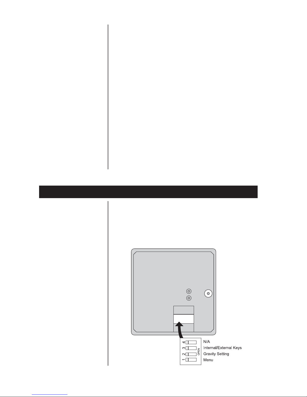
Top view of 7821 scale with platter removed.
Modes of Operation
Performing a Normal
Weighment
Accessing the Menu
If everything is OK, the display will show zero
weight and the scale is ready for use. If an error
was detected, it will be reported by an error code
as described in the section Error Codes. If the
scale is outside the ± 10% zero window, center
dashes are displayed “_ _ _ _.” Recalibration
may be required.
1. With the scale powered on, make sure the
scale platter is empty and the display is at
zero. If it not, press the ZERO key…
0.00 is displayed.
2. Place an item to be weighed on the scale
platter…
The scale will display the gross weight.
3. Remove the item from the scale platter.
The 7821 powers up in normal weighing mode
ready for weighing operations. Access the MENU
Mode by setting Switch 1 shown in Figure 1 to
the OPEN or MENU Mode position.
Figure 1
7821 Switch
Location

Model 7821 Bench Scale User’s Manual 7
There are three modes available to you with
Switch 1 in the MENU Mode or OPEN position.
They are as follows:
Diagnostic Mode – Used to test areas of the
scale’s function
Configuration Mode – Used to configure the
scale for your application
Calibration Mode – Used when calibrating
the scale
The structure for these menus is shown in Figure
2. The following pages have specific information
about each mode and step-by-step instructions
for accessing them.
The ZERO key zeros the scale, and UNITS key
changes the unit of measure between lb and kg.
The NCI 7821 bench scale has an optional
remote display. Typically, the remote display is
used to display weight only (i.e., the ZERO and
UNITS keys are not operable). Alternatively, it is
possible to have operable ZERO and UNITS
keys on the remote display, but in so doing, the
keys must be disabled on the local (or internal)
display. To activate the ZERO and UNITS keys
on the remote display, set dip Switch 3 to the
OPEN position.
With Switch 2 set to OPEN, you can adjust the
local gravity value. Press the ZERO key to
increase the value or press the UNITS key to
decrease the value. See Gravity Adjustment
section for details.
Zero and Units Key
Display
Remote Display
Gravity Adjustment

Model 7821 Bench Scale User’s Manual
8
Figure 2
Menu Structure

Model 7821 Bench Scale User’s Manual 9
The NCI 7821 bench scale allows calibration of
the scale using less than full capacity weights.
The following tables show alternative weights that
can be used to calibrate the scale at its desig-
nated capacity. See Table 1 for alternate calibra-
tion span loads.
Table 1:
Alternative Calibration Span Points
Alternative Alternative
Capacity Calibration Capacity Calibration
(lbs) Weights (lbs) (kg) Weights (kg)
150 x .05 lb 10, 50, 150 60 x .02 kg 10, 30, 60
70 x .02 kg 10, 30, 70
75 x .02 kg 10, 30, 75
150 x .02 lb 10, 50, 150 75 x .01 kg 10, 30, 75
200 x .05 lb 10, 100, 200 100 x .02 kg 10, 50, 100
Table 2:
Baud Rate and Parity Options
Display Baud Parity
12 E 1200 Even
48 E 4800 Even
*96 E 9600 Even
192 E 19,200 Even
12 o 1200 Odd
48 o 4800 Odd
96 o 9600 Odd
192 o 19,200 Odd
12 n 1200 None
48 n 4800 None
96 n 9600 None
192 n 19,200 None
*Factory Default Setting
Alternative Calibration
Span Points
Baud Rate and
Parity Options
Model 7821 Bench Scale User’s Manual
10
Diagnostics Mode
Scale lb/kg
Capacity and
Count-by Choices
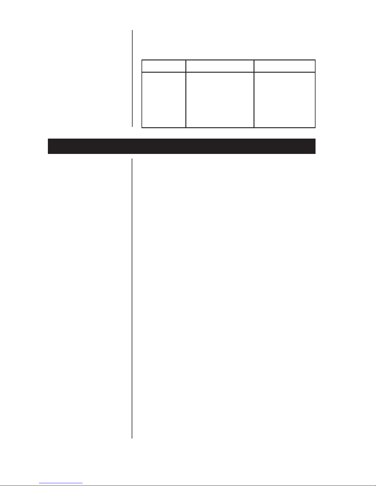
Table 3:
Scale lb/kg Capacity and Count-by Choices
Capacity (lb) Capacity (kg)
150 - 1 150 x .05 60 x .02
150 - 2 150 x .05 70 x .02
150 - 3 150 x .05 75 x .02
150 - 4 150 x .02 75 x .01
200 200 x .05 100 x .02
The Diagnostic (DIAG) Mode menu lets you test
specific areas of the scale’s function. These
areas are:
Display (DISP) – Shows the version and
revision of the software, followed by a display
segment test.
RAM (RA) – Performs a nondestructive test
of RAM in the processor. Displays PASS or
FAIL.
ROM (RO) – Performs a checksum of all
locations of ROM in the processor. Displays
PASS or FAIL.
Input/Output (I/O) – Data is output by the scale,
and through the use of a loopback connector, the
data is immediately read back into the receive
channel and verified against what was sent.
PASS or FAIL is displayed. Requires a jumper
(short) between transmit and receive data lines.
Division, Test w/AZT (HRESA) – Weight data is
normalized to 100,000 counts of displayed
resolution. AZT is enabled. Typically used by
service technicians.
Division, Test w/o AZT (HRESN) – Weight data
is normalized to 100,000 counts of displayed
resolution. AZT is disabled. Typically used by
service technicians.
Tabla de contenidos
Otros manuales de Escala de NCI

NCI
NCI 6702-7 Manual de usuario

NCI
NCI 7050 Manual de usuario

NCI
NCI 7820 B Manual de usuario

NCI
NCI 7050 Manual de usuario

NCI
NCI 7815 Manual de usuario

NCI
NCI 7815 Manual de usuario

NCI
NCI 7620 Family Manual de usuario

NCI
NCI 7820 B Manual de usuario

NCI
NCI 6720 Manual de usuario

NCI
NCI 6712 Manual de usuario


