max mobility SmartDrive Manual de usuario

5425 crossings boulevard, nashville, tn 37013p: 800.637.2980 f: 888.411.9027
mobility
max ®
Axle Clamp Mounting Instructions
NOTE: Refer to the separate directions provided for a folding frame
wheelchair.
CAUTION: e front and back of the
clamp will not mate even when the screws
are suciently tight. As shown in the
graphic below (Fig. B), there should be a
gap between the two parts. Over-tighten-
ing of the screws [more than 4 ft-lbs (5.4
N-m)] could cause the parts to break during
installation.
Fig. B
Fig. A
Clamp Mounting
e SmartDrive adaptive axle clamp is designed to permanently
mount to the axle tube of a rigid wheelchair while presenting a
simple means of attaching/removing the drive unit.
First, verify that the proper clamp is being used based on the
wheelchair rear wheel size. is is noted on the front / back of
protrusions (Fig. A). Refer to the chart below for proper clamp
usage:
22” (501) Wheel / Tire Use 24 clamp
24” (540) Wheel / Tire Use 24 clamp
25” (559) Wheel / Tire Use 25 clamp
26” (590) Wheel / Tire Use 26 clamp
ere are 2 dierent styles of clamps, standard tube [less than
1.4” (36 mm)] and large tube [greater than 1.5” (38 mm)]. Slide
the provided hard rubber inserts over the axle receiving tube to
accommodate smaller tube diameters (see chart below for sizing).
Dots on the side of the rubber inserts are used to identify the
tube size they t:
Rev. MX2 CM-D

Standard Tube Diameters
No Inserts 36 mm
No Dots 1.35”/1.375” or 35 mm
• 1.25” or 32 mm
•• 1.125” or 30 mm
••• 1.0” or 25 mm
Large Tube Diameters
No Dots 2” or 50.8 mm
• 1.77” or 45 mm
•• 1.5” or 38 mm
Use a 5 mm allen wrench to tighten the two (2) screws to mount the clamp to the axle re-
ceiving tube. e position and orientation outlined below are critical to the proper function
of SmartDrive and must be heeded.
Make sure the “max” on the front of the clamp is right-side up. Use the provided bubble
level and attach to one of the posts to assist you in getting the clamp level (Fig. C). e
protrusions coming from the side of the clamp are to be positioned rearward with the extru-
sion ats perpendicular to the ground when the chair [with the user in it] is on a level plane.
e clamp must be positioned midway between the two rear wheels of the wheelchair on
the axle receiving tube (Fig. D). e two (2) screws should be tightened to 4 ft-lbs (5.4
N-m), xing it in this position and orientation. Failure to do this could cause the wheelchair
to not drive/ride straight and/or the clamp to move during use causing the SmartDrive to
not function properly.
Adjustments made to the wheelchair set-up could aect the orientation of the SmartDrive clamp.
Adjust the clamp whenever changes are made to the chair.
Fig. D
Fig. C

Drive Unit Attachment
Making sure the wristband is o, power on the drive unit by ipping the toggle switch to the on position prior to attachment. “On”
is pushing the toggle away from the front of the drive unit (Fig. E). You will get a loud beep and the blue LEDs will illuminate as
indication.
1. e drive unit attaches to the wheelchair by aligning the ats in the clamp with the receiving slots on the front, underside of the
unit body. e unit body is then lowered over the clamp rods (Fig. F) and rotated downward to pivotally attach the drive unit to
the clamp, and consequently the wheelchair (Fig. G). Under the weight of the drive unit, the omni-wheel end rests on the ground
between the rear wheelchair wheels (Fig. H).
Fig. E
Fig. F
Fig. G

5425 crossings boulevard, nashville, tn 37013p: 800.637.2980 f: 888.411.9027
mobility
max ®
2. If buttons were purchased, refer to their separate instructions for mounting directions.
e buttons plug into to the drive unit us-
ing the magnetic connector that snaps into the receptacle on the drive unit housing (Fig. I).
Fig. H
Fig. I
Removal of the SmartDrive takes place in the reverse order.
Refer to the User’s Manual for SmartDrive operation.

5425 crossings boulevard, nashville, tn 37013p: 800.637.2980 f: 888.411.9027
mobility
max ®
Nederlands
Asbuis klem/connector instructies
Opmerking: Voor een rolstoel met vouwframe, raadpleeg de aparte meege-
leverde handleiding hiervan.
Monteren van de klem/connector
Fig. A
De klem/connector van de SmartDrive is ontworpen om permanent
te worden bevestigd aan de asbuis van een vastframe rolstoel, terwijl
het tegelijkertijd een gemakkelijke aan- en afkoppeling van de aandri-
jfunit mogelijk maakt.
Allereerst, controleer of de juiste klem wordt gebruikt gebaseerd op
de wielmaat van de rolstoel. Dit staat op de voor/achterkant van de
uitsteeksels (Fig. A). Raadpleeg onderstaande tabel:
22” (501) Wiel / Band
24” (540) Wiel / Band
25” (559) Wiel / Band
26” (590) Wiel / Band
Gebruik 24 klem
Gebruik 24 klem
Gebruik 25 klem
Gebruik 26 klem
Fig. B
Er zijn 2 verschillende stijlen van klemmen, standaard buis [minder
dan 1,4” (36 mm)] en grote buis [groter dan 1,5” (38 mm)]. Bij
kleinere asbuis diameters: kies uit de meegeleverde harde rubber
inzetstukken de meest passende maat en schuif deze over de asbuis
(zie onderstaande graek voor de maatvoering). Op de zijkant van de
rubber inzetstukken staan punten om aan te geven op welke diameter
asbuis deze past:
LET OP: Wanneer de schroeven voldoende
aangedraaid zijn zullen de voor- en de
achterkant van de klem elkaar niet raken.
Zoals hieronder afgebeeld (Fig. B) moet er
ruimte overblijven tussen de twee delen. Te
hard aandraaien (meer dan 5,4 Nm) kan de
delen doen breken tijdens de montage.

Standaard buisdiameters
Geen inserts
Geen punten
•
••
•••
36 mm
1.35”/1.375” of 35 mm
1.25” of 32 mm
1.125” of 30 mm
1.0” of 25 mm
Grote buisdiameters
Geen punten
•
••
2” of 50.8 mm
1.77” of 45 mm
1.5” of 38 mm
Gebruik een 5 mm inbussleutel om de twee (2) schroeven aan te draaien om de klem
te bevestigen aan de asbuis. De positie en richting zoals hieronder aangegeven zijn
cruciaal
voor het correct functioneren van de SmartDrive en moeten worden gevolgd.
Zorg dat “MAX” op de voorkant van de klem rechtop staat. Gebruik hiervoor de
meegeleverde waterpas door deze te bevestigen aan één van de uitstekende delen
(Fig. C). De uitstekende delen aan de zijkant van de klem moeten naar achteren
worden geplaatst loodrecht ten opzichte van de grond, waarbij de stoel [met de
berijder erin] zich op een vlakke ondergrond bevindt.
De klem moet in het midden tussen de twee wielen van de rolstoel op de asbuis
worden aangebracht. De twee (2) schroeven moeten worden aangedraaid tot 5,4 Nm
om de klem daarmee in de juiste positie en richting vast te zetten. Doet u dit niet, dan
kan dit tot gevolg hebben dat de rolstoel niet rechtuit rijdt of stuurt en/of dat de klem
beweegt tijdens gebruik, met als gevolg dat de SmartDrive niet goed functioneert.
Fig. C
Fig. D
Aanpassingen aan de rolstoel kunnen gevolgen hebben voor de positie of richting van de klem van de
SmartDrive. Stel de klem dus bij, iedere keer als er veranderingen aan de rolstoel zijn aangebracht.

Bevestiging van de aandrijfunit
Zorg ervoor dat de polsband is uitgeschakeld, schakel de aandrijfunit aan door de tuimelschakelaar in de AAN positie te zetten voor-
dat u deze aan de rolstoel bevestigt. “AAN” is wanneer de schakelaar, gezien vanaf de voorzijde van de aandrijfunit, omhoog staat (Fig.
E). U krijgt een luide pieptoon te horen en de blauwe LEDs zullen gaan branden als indicatie.
Fig. E
1. Om de aandrijfunit aan de rolstoel te bevestigen moet u de uitstekende delen van de klem/connector uitlijnen met de beve tigings-
gleuven aan de voorkant van en onderaan de aandrijfunit. Laat vervolgens de aandrijfunit over de uitstekende delen van de klem
zakken (Fig. F). Draai de unit naar beneden, zodat de unit scharnierend wordt bevestigd aan de klem en daarmee aan de rolstoel
(Fig. G). Door het gewicht van de aandrijfunit zal het omni-wiel van de aandrijfunit op de grond rusten tussen de achterwielen
van de rolstoel (Fig. H).
Fig. F
Fig. G

5425 crossings boulevard, nashville, tn 37013p: 800.637.2980 f: 888.411.9027
mobility
max ®
Fig. H
2. Wanneer u de optionele bedieningsknoppen heeft aangeschaft, raadpleeg voor de bevestiging hiervan de meegeleverde instructies.
Deze sluit u aan door de magnetische stekker in de ontvanger op de behuizing van de aandrijfunit te klikken. (Fig. I).
Fig. I
Het verwijderen van de SmartDrive gebeurt in de omgekeerde volgorde.
Raadpleeg de gebruikershandleiding voor de bediening van de SmartDrive.

5425 crossings boulevard, nashville, tn 37013p: 800.637.2980 f: 888.411.9027
mobility
max ®
Instructions de montage du support d’essieu
REMARQUE : Référez-vous aux directions fournies séparément pour
un fauteuil roulant à cadre pliant.
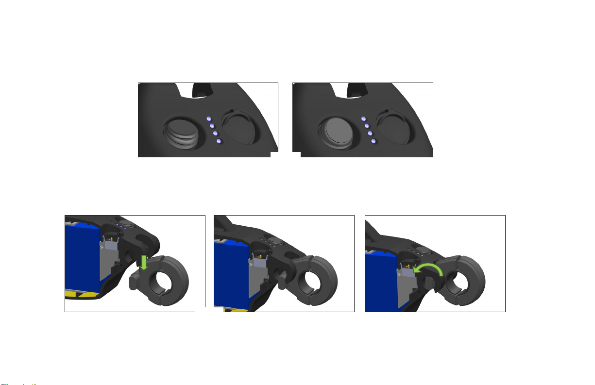
MISE EN GARDE : L’avant et l’arrière
du support ne se joignent pas même lorsque
les vis sont susamment serrées. Comme le
montre le graphique ci-dessous (gure B), il
doit y avoir un écart entre les deux parties.
Un serrage excessif des vis [plus de 4 ft-lbs
(5,4 N-m)] pourrait provoquer la rupture
des pièces pendant l’installation.
Fig. B
Fig. A
Montage du support
Le support d’essieu adaptable de SmartDrive est conçue pour être
montée de manière permanente sur le tube d’essieu d’un fauteuil
roulant rigide tout en présentant un moyen simple de xer/retirer
l’unité d’entraînement.
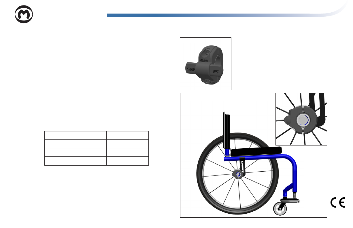
Tout d’abord, vériez que le support approprié est utilisé en fonc-
tion de la taille de la roue arrière du fauteuil roulant. Cela est noté
sur l’avant/l’arrière des protubérances (gure A). Reportez-vous au
tableau ci-dessous pour une utilisation correcte du support:
Roue/pneu de 22” ou 56 cm (501) Utilisez un support 24
Roue/pneu de 24” ou 61 cm (540) Utilisez un support 24
Roue/pneu de 25” ou 63,5 cm (559) Utilisez un support 25
Roue/pneu de 26” ou 66 cm (590) Utilisez un support 26
Il existe 2 types de supports, à tube standard [moins de 1,4 “(36
mm)] et à tube large [supérieur à 1,5” (38 mm)]. Faites glisser
les inserts en caoutchouc dur fournis sur le tube de réception de
l’essieu pour s’adapter à des diamètres de tube plus petits (voir le
tableau ci-dessous pour le dimensionnement). Les points sur le
côté des inserts en caoutchouc sont utilisés pour identier la taille
du tube auquel ils correspondent:
Français

Diamètres de tube standard
Pas d'insert 36 mm
Pas de point 1,35”/1,375” ou 35 mm
• 1,25” ou 32 mm
•• 1,125” ou 30 mm
••• 1,0” ou 25 mm
Diamètres de tube large
Pas de point 2” ou 50,8 mm
• 1,77” ou 45 mm
•• 1,5” ou 38 mm
5 mm pour serrer les deux (2) vis servant à monter la pince sur le tube de réception de
l’essieu. La position et l’orientation décrites ci-dessous sont essentielles au bon fonc-
tionnement de SmartDrive et doivent être prises en compte.
Assurez-vous que le “MAX” sur le devant du support soit positionné à droite et vers le haut.
Utilisez le niveau à bulle fourni et xez-le à l’un des montants pour vous aider à obtenir le
bon niveau de serrage (Fig. C). Les protubérances venant du côté du support doivent être
positionnées vers l’arrière avec les méplats d’extrusion perpendiculaires en direction du sol
lorsque la chaise [avec l’utilisateur] est sur un plan horizontal.
Le support doit être positionné à mi-chemin entre les deux roues arrière du fauteuil sur
le tube de réception de l’essieu (Fig. D). Les deux (2) vis doivent être serrées à 4 ft-lbs
(5,4 N-m), en les xant dans cette position et cette orientation. Si vous ne le faites pas, le
fauteuil roulant ne roule pas, ou ne roule pas droit et/ou le support ne bouge pas pendant
l’utilisation, ce qui empêche le SmartDrive de fonctionner correctement.
Les ajustements apportés aux réglages du fauteuil peuvent aecter l’orientation du support de SmartDrive. Ajustez le support
chaque fois que des modications sont apportées au fauteuil.
Fig. D
Fig. C
Tabla de contenidos
Idiomas:
Otros manuales de Silla de ruedas de max mobility
max mobility
max mobility SmartDrive MX2 Manual de usuario

max mobility
max mobility SmartDrive MX2 Manual de usuario

max mobility
max mobility SDMX2-DUM Manual de usuario

max mobility
max mobility SmartDrive MX2+ Manual de usuario

max mobility
max mobility Folder Adaptor Bar Manual de usuario
max mobility
max mobility Thumb Throttle Button Manual de usuario

max mobility
max mobility SmartDrive MX2+ Manual de usuario

max mobility
max mobility smartdrive mx1+ Manual de usuario

max mobility
max mobility SmartDrive MX1 Manual de usuario


