Note3) Zero adjustment error alarms regardless of the “Enable” / “Disable” of the alarm.
·
If a zero-set input of longer than 5seconds is input the Baud rate will be set to 9600bps and other
communication protocols will be returned to initial value (factory shipped value).
10. Operation
(1) Procedure
1) This product is packed in a clean room before shipment. Please break the
seals in a clean room after taking it out of its box.
2) Check the gas type and flow rate, and check the direction of the gas flow
and the MFC before installation.
3) Check for gas leaks from the tubing with a helium (He) leak detector.
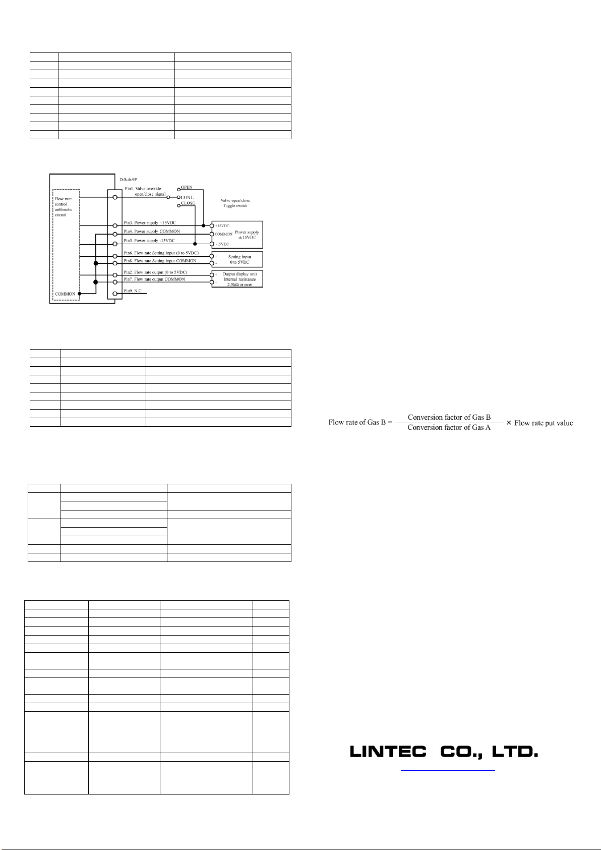
4) Connect the interface connectors according to the Connector tale.
5) Power requirements are +15VDC: 100mA and -15VDC: 50mA. Check the
voltage, polarity, and capacitance of the power supply voltage.
6) Turn on power supply and let the equipment warmup for at least 5 minutes
(Recommended time: 30min).
7) Adjust the zero point by pressing the zero adjustment, switch located on
the top of the MFC. Before zero-point adjustment, check that gas is not
being supplied and the device was warmed up for 30 minutes or more in
order to ensure sensor stability.
8) Input the flow rate setting signal and supply gas with required differential
pressure to the MFC. The MFC will begin to control the gas flow in
proportion to the preset voltage. Full-scale voltage is 5VDC. Maximum
input voltage is ±15.5VDC.
9) When the output flow rate signal is used, the tolerance voltage of the
external device should be more than ±15.5VDC. When it’s connected the
output valve may be within the range of the maximum voltage ±15.5VDC.
10)Complete shut off cannot be achieved with the mass flow controller. If
complete shut off is desired, a shut-off valve should be installed.
11)When a highly reactive gas is used, thoroughly purge all foreign matter
from the tubing and the MFC before operation.
12)When contaminated gas is used, install a filter at the equipment inlet.
13)Use the MFC within the range of the operating temperature (5 to 50°C),
and keep it at the same temperature with the gas. If used in any
environment that does not meet the above-mentioned requirements, the
flow rate cannot be measured accurately and the device may fail.
14)Donotswitchthepowersupplyonandoffwithinonesecond.Itmaycausefailure.
(2) Valve control signal
The MFC features a forced valve open/close input function.
The connector pin No.1 is used to input the internal valve open/close signal.
By inputting this signal, a forced opening/closing of the internal valve can be
performed without depending on the value of the flow rate preset signal.
When +15VDC is input: fully open
When –15VDC is input: fully closed.
(3) Conversion factor
The MFC is preset based on the kind of gas and the flow rate. If a gas that is not
specified is supplied, the controlled flow rate may be different from the actual
flow rate. This difference is called a conversion factor, and is normally
represented by a ratio with N2. When gas B is fed into the MFC, which was
calibrated with gas A, the controlled flow rate is shown below.
The accuracy of this value may be decreased if the character of the gas is
greatly different. Also, the value of the MFC has been adjusted based on the
viscosity and density of the gas, therefore if a gas other than the calibration gas
is applied, the operating pressure range may be altered. The conversion factor
can be set at any desired value, with an operating range of 0.6666 to 1.5000. If
the conversion factor value exceeds this range, the operation of the MFC
become unstable. The accuracy is different from the standard specifications of
the MFC, when the conversion factor is changed.
(4) Digital interface
The MFC features the RS-485 serial digital interfaces. Many special functions
can be employed using the digital interfaces. Please refer to other manuals
(Digital Interface Manual, Special Function Manual, Command Chart).
11. Product warranty
(1) Period
This product is guaranteed for a period of 1 year from date of shipment. Defects
are repaired according to the following regulations.
(2) Scope
Warranty coverage is restricted to this product only. Any other damage caused
by this product is not covered.
(3) Disclaimer facts
The following repairs are not covered by the warranty:
1) Failure caused by by-product of fluid used.
2) Failurecausedbymisuse(includingcarelessoperation)orincorrectrepairormodification.
3) Failure caused by dropping after purchasing.
4) Failure caused by a natural disasters.
Even if the warranty period isstill in effect, the following items may not be repaired.
1) When the kind of fluid used in the product is unclear.
2) The product is returned with fluid remaining inside and safety cannot be
confirmed.
The MFC is a precision instrument. Control may become unstable if electric
noise, temperature change of fluid, pulsation of fluid pressure etc. occurs.
Please be forewarned.
This instruction manual is subject to revision without notice.
http://www.lintec-mfc.co.jp
CorporateHeadquarters
4-1-23 Sekinotsu,OtsuCity, ShigaPref.520-2277,Japan
TEL. +81-(0)77-536-2210FAX.+81-(0)77-536-2215
TokyoBranchOffice
3FHattoriBuild.,4-30-14YotsuyaShinjyuku-kuTokyo160-0004,Japan
TEL. +81-(0)3-5366-2801FAX.+81-(0)3-3341-3513