LAPLACEINSTRUMENTSLTD RF300 USER GUIDE
Page10
8. Theloops can nowbeadjusted forbestshapeand position. Generallythevertical
loops will tend to saginto thelower halfoftheantenna. Theseare held up in position
byusingthetiewraps as shown in fig8 on each corner postto takesomeon theweight
oftheloop. Thetop oftheverticalloops can beadjusted forbestshapeand thetwo
loops fastened together with thefifth tiewrap. With care, thetiewraps can beadjusted
to produce reasonablecircles foreach loop.
Notethattheexactshapeis notcritical. Deviation fromperfectcircles is inevitablebut
this has no significanteffecton antennaperformance. EN55015 states in section 7.2
thateven theposition oftheUUT in theantennais notcritical.
9. Within theloop, constructawooden stand ortableto suit theproducts to betested.
This is notincluded with theRF300 becauseit needs to bematched to individual
customers requirements. Thestand should hold theproductroughlycentralwithin the
loop.
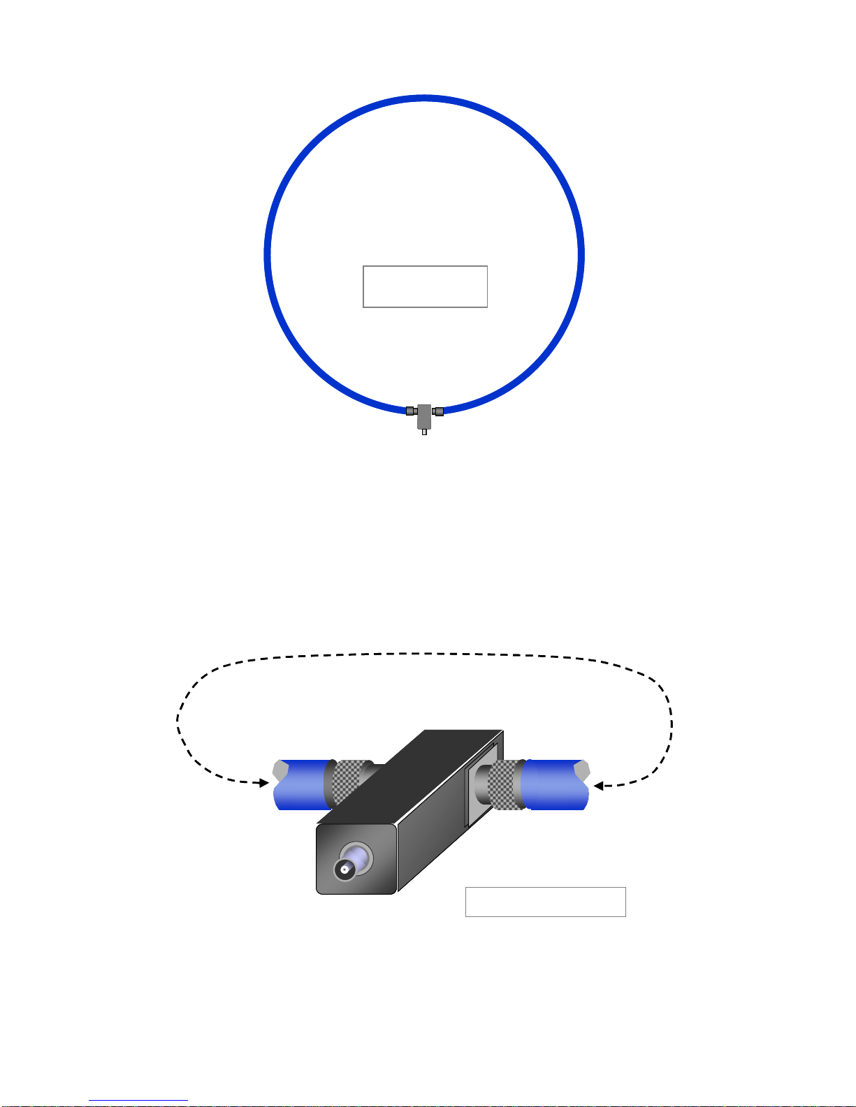
10. Connecttheloop transducers to theswitch unit as shown in fig11. The3
transducer cables are identified byhavingthick RFabsorber filters alongtheirlength.
Fit thecables so thatthesefilters are nearestto theswitch unit.
Theswitch unit is intended forfloormounting, ormaybemounted on asuitabletable
ifpreferred. Theshortco-axcableacts as apatch cableto switch each input, oneata
time, to theoutput.
Theoutputfromtheswitch unit is connected directto theanalyser orreceiver.