Kiturami KRH-35B Guía del usuario

┃┃┃┃┃
Model
* KRH - 35B (40.6 kW)
Technical information and Installation Servicing Instructions
NEW Hybrid
Wood fired Boiler...
........
1페이지

CONTENTS
1) OVERALL VIEW
1-1 GENERAL INFORMATIONGeneral Information
******************************************* 3
2) PRODUCT DESCRIPTION
2-1 SPECIFICATION ******************************************* 4
3) INSTALLATION
3-1 STANDARD INSTALLATION ******************************************* 5
3-2 INSTALLING FLUE ******************************************* 6
3-3 HEATING PIPE CONNECTION ******************************************* 8
3-4 TOTAL PIPE WORK ******************************************* 10
3-5 CONNECTION ELECTIRICITY ******************************************* 11
4) TEST WORKING
4-1 CHECK LIST BEFORE SWITCHING ON ******************************************* 12
4-2 HOW TO IGNITE FIREWOOD INITIALLY ******************************************* 13
5) DIRECTION FOR ASSEMBLY
5-1 DISASSEMBLY ******************************************* 14
5-2 PART LIST ******************************************* 15
6) FUNCTIONS OF THE CONTROLLER
6.1 MAIN CONTROLLER PART NAME ******************************************* 16
7) FUNCTION OF THE CONTROLLER
7-1 ROOM CONTROL PANEL (CTR-5700 PLUS) ******************************************* 18
7-2 ROOM CONTROL PANEL ******************************************* 19
8) TROUBLESHOOTING GUIDE (error code) ******************************************* 27
8-1 FINDING FAULT ******************************************* 20
9) TECHNICAL DATA TABLE ******************************************* 21
10) MEMO ******************************************* 22
11) WARRANTY ******************************************* 23
2페이지

IMPORTANT TIPS
* Read this instruction manual carefully before you start to install and use the boiler, what is the
condition of the efficient use and the proper installation of the appliance.
* This instruction manual is an integral and important equipment of the boiler. They should be kept
through the whole operation life of the boiler and should be read carefully as it includes full
information and warnings concerning safety during installation, operation and maintenance,
which must be observed.
* Flue system must be tight. Leakage on the pipe connections may cause flood the interior of the
boiler with the condensate. All damages and defects of boiler cause by above situation are excluded
of the producer's responsibility.
* The boiler can be installed and operated only in a room where all building works have been already
completed. It is not allowed to install and operate the boiler in a room where building works are still
in progress. The cleanliness of air in a room where the boiler will be installed must meet the same
requirements as for rooms designed for people.
* All defects caused by a lack of filters on central heating or domestic water systems neither gas supply
will not be repaired under quarantee.
* The first boiler start - up as well as its repairs, adjustments and maintenance works must be only
performed by a qualified person.
* The boiler must be operated by adult only.
* Do not do any repairs and modifications by yourself.
* Do not cover the air grates.
* Do not keep in the vicinity of the boiler any containers with flammable, aggressive and corrosive
liquids and other substances.
* Any failures that are a result of operation discordant to recommendations included in this instruction
manual cannot be cause for complaint.
* Manufacturer is not responsible for any failures being the result of faults during the process of
installation and inobservance the regulations and instructions given by the manufacturer.
* Complying with recommendations given in this instruction manual ensures a long, reliable and
safe operation of the boiler.
3페이지

1. OVERALL VIEW
These instructions are suitable for KRH Series hybrid Wood fired boiler;
Do not forget this instruction.
To ensure the correct installation, commissioning and servicing of domestic central heating system.
NEW CONCEPT & NEW TECHNOLOGY
1. Exhaust / intake phase modulation system
As ventilation quantity is modulated by MCU that checks the rising speed of water temperature in real time, the
optimum combustion condition and long heating are realized.
2. The advanced exhaust / intake system
The exhaust/intake system is applied to wood fired boiler for the first time in the country so as to prevent backfire in the
combustion chamber during combustion. Thus, the internal pressure of combustion chamber becomes negative(minus)
and fan operates only when necessary, i.e., turbo system that increases heat power in the shortest time is applied.
3. The first domestic oil igniting system
After supplying firewood, there is no need to take pains to ignite it, but firewood can be easily ignited only with igniting
button.
4. special hot water coil heat exchange system of high efficiency
As hot water heat exchanger is placed at the highest positon (highest temperature part), boiling in the internal box of
boiler is prevented and abundant hot water can be used. Since hot water of heat exchanger flows up and down in
double structure, heat exchange rate is increased to supply sufficient water for bath.
5. hybrid systems of firedwood and oil
As firewood combustion is detected by internal sensor, oil burner automatically operates when combustion stops so as
to supply heat for heating.
6. Heat exchange system of high efficiency
As water tube grate and upper fire tube are installed inside, combustion gas is emitted after heat is fully exchanged inside
heat exchanger.
1-1 INFORMATION
4페이지

2. PRODUCT DESCRIPTION
Model : KRH-35A
Room Control
DIMENSION (Wx Dx H)
Model
FUEL TYPE
HETING AREA
(㎡)
INSTALLATION TYPE
Wood & oil
AC 220V ~ 230V/ 50Hz
Floor standing type
WEIGHT (kg)
POWER SOURCE
300
1-1 SPECIFICATION
740 X 1,343 X 1,380 mm
FLUE
3.7
5페이지

3. INSTALLATION
1. dimension
용량 A B C D E F G H I
KRH-35A 1051 780 1000 165 214 376 135 135 135
2. Pipe size
DHW INLET
DMH OUTLET
1 1/4 " (32)
CH OUTLETCH SUPPLY
1/2" (15) 1 1/4 " (32)KRH - 35A 1/2" (15)
REMARK
3-1 STANDARD INSTALLATION
1/2" (15)
SAFETY VALVECAPACYTI
6페이지

3. INSTALLATION
▶ In case of existing flue ▶ In case of no existing flue
* In using a flue, Check the status of flue every 6 months, * Install the flue 3m above the boiler along with
replace it when there is much soot in it. a “T” unit at the end of the flue in order to
prevent incomplete combustion caused by
damaging winds.
▶ Cautions in installing Flue
▶ Install the flue in such a way that the flue is free from the wind pressure zone, rain or wind
Warning: Installation of additional flue
1. Clearance greater than 30 cm should be ensured from the flue to
prevent contact with combustible materials, and the flue should be
finished with incombustible materials
2. Sudden heat may be emitted by the flue when supplying sthe fuel.
Do not store inflammable or combustible materials in the vicinity of
the stove pipe. Install the flue, taking care to ensure sufficient clearance
from the flue.
<The distance length between rafters and ceiling>
3-2 INSTALLING FLUE
Install it with
downslope 5
degrees Drainage device
Install the device with
inclination of 5
degrees
Flue
Flue
1m or longer
T pipe
1m or longer
Drainage device
Shorter
than
1 m
Drainage device
3m or longer
1m or longer
Wind
pressure
zone
Flue
7페이지

3. INSTALLATION
▶ If there is a tall building or an obstacle within 1 m of the flue, install the flue 1 meter higher than
the roof of the building.
- Install the flue at a location 3 meters or higher than the top of the boiler
- The height of the installed flue should be greater than three times the horizontal length.
▶ If the flue is installed in a wind pressure zone, excessive soot resulting from incomplete combustion
may result, thus reducing operational efficiency, safety shutdown may be triggered, causing abnormal
operation of the boiler To prevent this, the flue should be installed in a position outside the wind pressure zone.
- Especially, when you use wood or coal fuel, you should avoid the wind pressure band.
The provision for satisfactory flue termination must be installed in accordance with local regulations.
The appliance must be installed so that the flue terminal is exposed to outdoor air.
The terminal must not discharge into another room or space such as an outhouse or lean-to. It is important that the
position of the terminal allows a free passage of air across it at all times. The terminal should be located with due
regard for the damage or discoloration that might occur on buildings in the vicinity,
it must also be located in a place not likely to cause nuisance. In cold or humidity weather water vapor may condense
on leaving the flue terminal The effect of such “steaming” must be considered. If the terminal is less than 1 meter
above a balcony, above ground or above a flat roof to which people has access, then a suitable stainless steel terminal
guard must be fitted. The minimum acceptable spacing from the terminal to obstructions and ventilation openings
are specified in Fig. X.
* Warning
The exhaust gas duct must not be contact with or close to inflammable material and must not pass through building
structures or walls made of inflammable material. When replacing an old appliance, the flue system must be changed.
3-2 INSTALLING FLUE
8페이지
3. INSTALLATION
2. Water connection
1) The illustration shows the connections for the water and gas attachments of the boiler. See valves configuration
2) Check that the maximum water mains pressure does not exceed 3bar; if it does, a pressure reducing valve must be
installed.
3) For measuring of the pipes and of the heating bodies in the heating system, the residual head value should be calculated
as a function of the requested flow rate, in accordance with the valves shown in the circulation pump graph
3. Drain connection
1) Extend the hose from the safety valve and connect the drain hole.
※ Caution : Do not store any wettable things under the boiler or near the drain hole.
3-3 HEATING PIPE CONNECTION
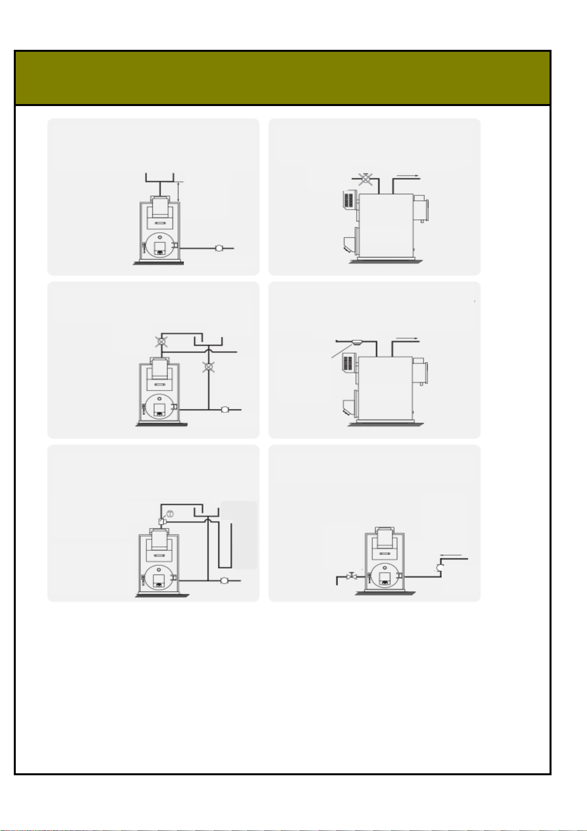
1. Install the expansion tank 1m higher than the top of
boiler. In installing it in a basement, Install it 1m higher
than the floor pipe.
2. Connect the Domestic Hot Water Inlet with water
storage tank, not with the water pipe directly.
3. Do not equip Water supplement pipe and Drain
pipe with the check valves.
5. Install expansion tubes at Heating water outlet and
Drain pipe by using Tee
* Install the expansion
tube without any curve.
* Use a tube more
than 20A as the
expansion tube.
6. Use the appropriate capacity of circulation pump,
and install a drain valve.
4. Keep the pressure of DHW inlet within 0.6 ∽ 1kg/
㎠. Install a pressure reducing valve when or
connecting it to water supply pipe directly. using a feed
pump
hot water tank
expansion
vessel
hot water oulet
piping
directly
higher than
1m
the side
the side
Check
valve
Circulation pump
nitrogen
vessel
20A tube
use a relief
pressure valve
Circulatio
n pump
heating
water
return
oulet
valve
Check
valve
nitrogen
vessel
Circulation pump
Piping to
prevent
natural
circulation
9페이지

3. INSTALLATION
3-4-1 STANDARD PIPE WORK
3-4 TOTAL PIPE WORK
<DOWNWARD PLUMBING TYPE>
T unit for preventing rainwater
Water supply
3M or longer
Hot water outlet
Nitrogen tank (20L or
more)
Heating water
outlet
distributor
Heating water
collection and
distribution unit
Exhaust drain
Safety
valve
Expansion pipe( higher than heating
pipe)
Hot water
outlet
Hot water
inlet
Heating
outlet
10페이지
Otros manuales para KRH-35B
1
Tabla de contenidos
Otros manuales de Caldera de Kiturami

Kiturami
Kiturami TURBO CONDENSING - 13 Manual de instrucciones

Kiturami
Kiturami KRH-35B Manual de usuario

Kiturami
Kiturami KRP-20PA Manual de usuario

Kiturami
Kiturami K1-22E Manual de usuario

Kiturami
Kiturami KRP-20A Manual de usuario

Kiturami
Kiturami TURBO-21 Manual

Kiturami
Kiturami KF-35B Manual de usuario

Kiturami
Kiturami KF Manual de usuario

Kiturami
Kiturami eco condensing - 16D Guía del usuario

Kiturami
Kiturami PELLET BOILER Manual de usuario


