inveo NANO IN Manual de usuario

User manual
Input reading module
NANO IN
Soft >= 1.0
INVEO s.c.
ul. Rzemieślnicza 21
43-340 Kozy
tel: +48 33 444 6 87
www.inveo.com.pl

Dear Customer!
Thank you very much for choosing our product. Please carefully read this user
manual as it contains most appropriate ways of dealing with this device, taking into
account the basic principles of safety and maintenance. Please also keep the user
guide that you can use it during subsequent use.
Manufacturer Liabilit !
The manufacturer is not liable for an damage caused b improper or
incompatible use of this device, as well for an faults to the device resulting
from improper use.
User manual NANO IN Page 2 of 22

Contents:
1 PRELIMINARY INFORMATION....................................................................................................................4
2 DEVICE DESCRIPTION ...................................................................................................................................5
3 WARRANTY AND LIABILITY OF THE MANUFACTURER ...................................................................5
4 SAFETY GUIDELINES .....................................................................................................................................6
4.1 POWER SUPPLY....................................................................................................................................................6
4.2 STORAGE, WORKING ENVIRONMENT AND TRANSPORTATION..........................................................................................6
4.3 INSTALLATION AND USE OF THE MODULE..................................................................................................................6
4.4 UTILISATION OF THE MODULE.................................................................................................................................6
5 MODULE DESCRIPTION.................................................................................................................................7
5.1 GENERAL FEATURES.............................................................................................................................................7
5.2 TECHNICAL SPECIFICATION ....................................................................................................................................7
5.3 MODULE INPUT/OUTPUT TERMINAL DESCRIPTION.....................................................................................................8
5.4 BINARY OPTO-ISOLATED INPUTS – CONNECTIONS.......................................................................................................8
6 MODULE CONFIGURATION..........................................................................................................................9
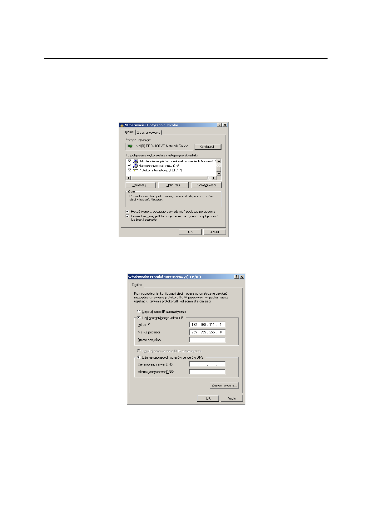
6.1 CHANGING THE PC SETTING FOR MODULE CONFIGURATION.........................................................................................9
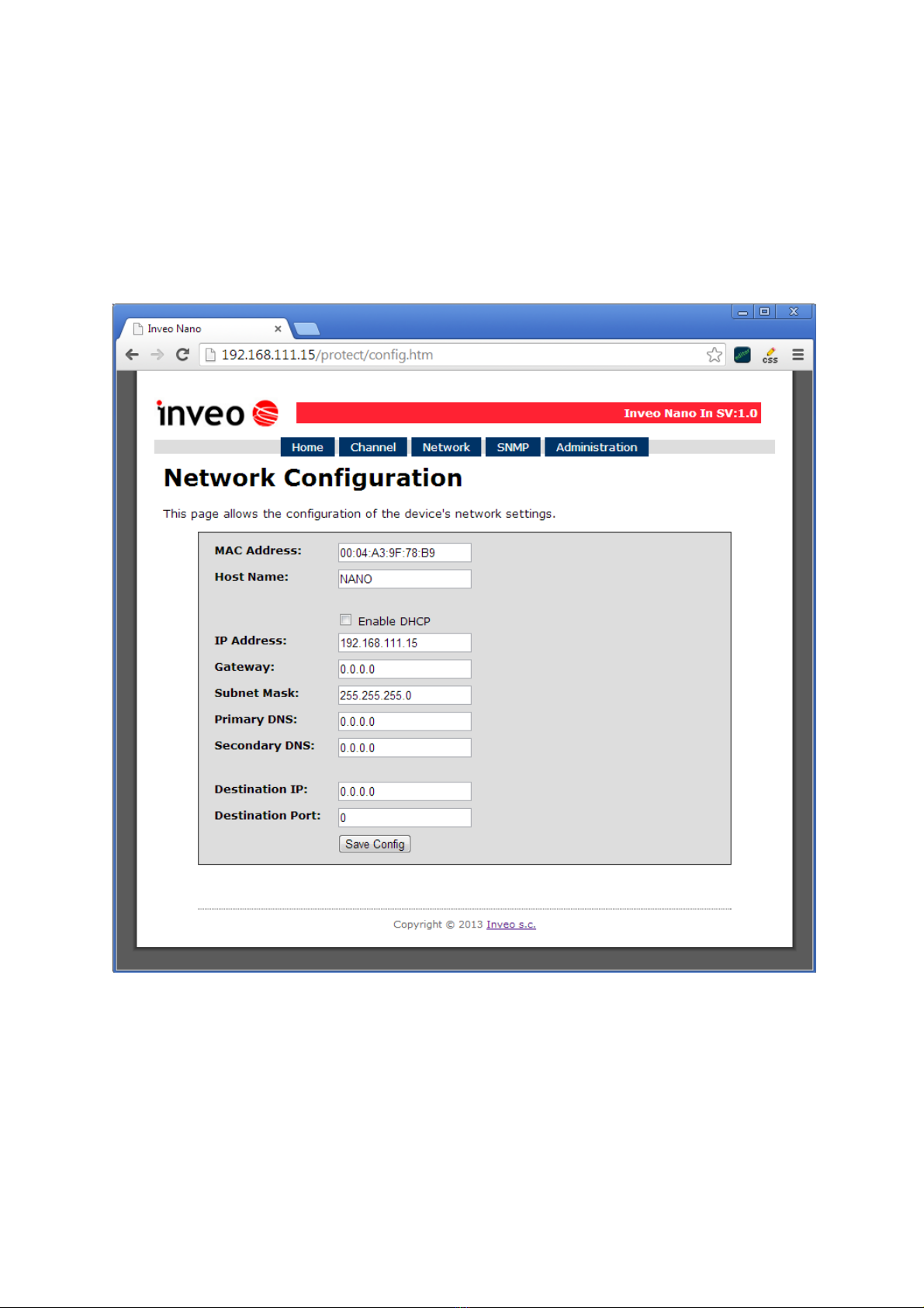
6.2 CONFIGURATION OF THE MODULE MODULE THROUGH WEB BROWSER...........................................................................10
6.3 INPUT READOUT.................................................................................................................................................11
6.4 ACCESS CONFIGURATION.....................................................................................................................................12
6.5 SNMP CONFIGURATION.....................................................................................................................................13
6.6 MANAGING THE MODULE USING WINDOWS COMMAND LINE SOFTWARE........................................................................14
6.7 MANAGING THE MODULE USING LINUX COMMAND LINE SOFTWARE............................................................................15
6.8 MANAGING THE MODULE USING MODBUS TCP.................................................................................................16
6.9 COMMUNICATION WITH MODULE USING HTTP.......................................................................................................17
6.10 COMMUNICATION PROTOCOL DESCRIPTION............................................................................................................18
6.11 COMMUNICATION WITH MODULE FROM OUTSIDE NETWORK .....................................................................................19
7 DHCP...................................................................................................................................................................2
8 RESTORING FACTORY DEFAULTS ..........................................................................................................2
9 FIRMWARE UPDATE.....................................................................................................................................21
NOTES..................................................................................................................................................................22
User manual NANO IN Page 3 of 22

1 Preliminar information
Before using the module please read the user manual carefull and follow the
instructions contained within!
Description of visual symbols used in this user manual:
This symbol is responsible for reviewing the appropriate place in the
user instructions, warnings and important information. Failure to
follow warnings could cause injury or damage to the module.
Important information and guidelines.
Following this guidelines makes the use of the module easier.
Attention: The appearance of the screen shots shown in this manual may differ
slightly from the actual work with the module. The differences may relate to the size
and font type and size of symbols. There are no differences in the content of the
information.
User manual NANO IN Page 4 of 22

2 Device description
The NANO IN device is used to read state of the input through LAN network. The readout
can be done using www website, network protocols or software supplied by
manufacturer.
3 Warrant and liabilit of the manufacturer
The manufacturer provides a 2-year warranty on the module. The manufacturer also
provides post-warranty service for 10 years from the date of the introducing the module
on the market. The warranty covers all defects in material and workmanship.
The manufacturer undertakes to comply with the contract of guarantee, if the following
conditions are met:
All repairs, alterations, extensions and device calibrations are performed by the
manufacturer or authorized service,
supply network installation meets applicable standards in this regard,
device is operated in accordance with the recommendations outlined in this manual,
device is used as intended.
The manufacturer assumes no responsibility for consequences resulting from improper
installation, improper use of the module, not following this manual and the repairs of the
module by individuals without permission.
This device doesn’t contain serviceable parts. The repairs can be done onl b
manufacturers approved repair service.
User manual NANO IN Page 5 of 22

4 Safet guidelines
The module has been constructed using modern electronic components, according to the
latest trends in the global electronics.
In particular, much emphasis was placed on ensuring optimum safety and reliability
of control.
The device has a housing with high quality plastic.
4.1 Power supply
The module power supply must be in range of 10-24V AC or DC.
The power to module is delivered via POE adapter (Power Over Ethernet).
4.2 Storage, working environment and transportation
The module has to be used in closed environments free from fumes and corrosive
atmosphere.
Environmental conditions for storage:
Temperature: + °C to +4 °C,
Relative humidity: <7 %,
Atmospheric pressure: 700 – 1060hPa.
Environmental conditions for use:
Temperature: +10°C to +30°C,
Relative humidity: 30% to 7 %,
Atmospheric pressure: 700 to 1060hPa.
Recommended conditions for transportation:
Temperature: -10°C to +4 °C,
Relative humidity: 20 to 9 %,
Atmospheric pressure 700 to 1060hPa.
4.3 Installation and use of the module
The module should be used following the guidelines shown in next part of the
user manual.
4.4 Utilisation of the module
When it becomes necessary to liquidate the device (e.g., after the time of use), please
contact the manufacturer or its representative, who are obliged to respond appropriately,
i.e., collecting the module from the user. You can also ask the companies involved
in utilization and / or liquidation of electrical or computer equipment. Under
no circumstances should you place the device along with other garbage.
User manual NANO IN Page 6 of 22

5 Module description
.1 General features
Overall view of the module is shown on the picture below.
Module input can work as a pulse counter
There are several ways to communicate with the module:
•using built in WWW server via any web browser,
•MODBUS TCP protocol,
•SNMP protocol,
•HTTP protocol,
•User application – communication protocol available for user
NANO module is equipped with two LEDs indication power and input status.
.2 Technical specification:
Power supply voltage: 10-24VDC (POE)
Power consumption: 1. W
Opto-isolated inputs:
Input voltage: 10-24V
Counter max value: 4 294 967 296
Max input requency: 1000Hz
LAN: Ethernet 1x10Mbps, RJ45
User manual NANO IN Page 7 of 22
NANO IN

.3 Module input/output terminal description
Module NANO IN has two connection terminals:
•RJ4 socket – LAN network and POE
•Screw terminal – input
.4 Binary opto-isolated inputs – connections
Typical binary input connection is shown below. When placing order customer can choose
option with pre-polarised traspotor diode or without pre-polarisation.
The opto-isolated input is designed to accommodate input voltages between 10 and 24 V.
User manual NANO IN Page 8 of 22
Binar input – connection schematic.

6 Module configuration
If using the module for the first time it is needed to configure it as shown below
6.1 Changing the PC setting for module configuration.
After connecting the module to the network there is a need to change the PC setting. In
order to do that navigate to: Start->Control Panel->Network connections.
Then right click on the current network connection and click „Properties”.
The configuration screen as shown below should be visible on the screen:
Choose the „Internet Protocol (TCP/IP)” and press „Properties”:
TCP/IP example settings
Tick the box „Use the following IP address” and enter:
IP address: 192.168.111.1
Subnet mask: 255.255.255.0
The rest of the setting can be left blank.
Press OK to accept the changes.
User manual NANO IN Page 9 of 22

6.2 Configuration of the module module through web browser
Start the web browser and enter the following address into address bar:
192.168.111.15.
The default user name is „admin” with password „admin00”
There are several fields used to configure the module network settings:
MAC Address – MAC address of the module,
Host Name – NETBIOS host name of the module,
Enable DHCP – When this box is ticked the module will get its address from DHCP
server,
IP Address – IP address of the module – when configured manually,
Gateway – Network gateway,
User manual NANO IN Page 10 of 22
Network connection setup
Tabla de contenidos
Otros manuales de Unidad de control de inveo
Manuales populares de Unidad de control de otras marcas

Festo
Festo Compact Performance CP-FB6-E Manual de lista de piezas

Elo TouchSystems
Elo TouchSystems DMS-SA19P-EXTME Manual de usuario

JS Automation
JS Automation MPC3034A Manual de usuario

JAUDT
JAUDT SW GII 6406 Series Guía rápida

Spektrum
Spektrum Air Module System Manual de usuario

BOC Edwards
BOC Edwards Q Series Manual de usuario


