Improved Racing EFR-605 Manual de usuario

1996-2004 Ford Mustang gt oil
Filter relocation Kit
Part no. eFr-605
MADE IN USA
For contact informaon, visit www.improvedracing.com
Copyright © 2008-2020 Improved Racing Products, LLC. All rights reserved.
Rev 200421
Important: Read these instrucons in their
enrety prior to installaon.

Visit www.improvedracing.com for addi onal support
2
aPPlications
• 1996-2004 4.6L Ford Modular V8 Mustang GT, chassis code SN95
•
Cobra and Mach 1 trims require an op onal 1.75” to 1.50” radiator hose
reducer (sold separately). The included silicone radiator hose must also
be trimmed for these applica ons.
Parts list & HardWare
Qty Part Number Descrip on
1 EFR-100 Remote Oil Filter and Cooler Adapter, Ford 4.6 & 5.4
Modular V8 Engine
1 EFR-800 Radiator Hose, with Clamps
4 OM-10-10 -10AN ORB to -10AN Male Adapter Fi ng
1 OB-16-28 -16AN ORB to 1.75” Hose Barb Adapter Fi ng
1 ENV-140-F4 Remote Oil Filter Mount, M22x1.50 Filter Thread, with
Moun ng Brackets
2 EFR-600-50 Pre-assembled Oil Lines
1 EFR-600-62 Oil Line Hardware Pack
beFore you begin
WARNING:Thisproductshouldonlybeinstalledbyaqualifiedme-
chanic.Improperinstallaoncouldresultinsevereenginedamage.
Tip: Use aluminum tools to avoid damaging ngs.
Lubricate all ng ares for a be er seal.
Wrap tapered pipe (NPT) threads with Te on (PTFE) tape or apply thread
sealant to seal the threads.

Visit www.improvedracing.com for addional support 3
Lubricate O-rings prior to installaon to prevent damage and ensure a
leak-free seal.
PreParing For installation
1. Raise the front of the vehicle and support with approved automove
frame stands, li, or ramps.
WARNING:NEVERworkunderavehiclesupportedonlybyajack.
2. Remove any underbody panels necessary to access the oil lter.
3. Place a drain pan under the lter, remove the oil lter and allow the oil
to drain.
Cauon:Oilmaybehot!
4. Remove the front bumper cover and head lights to gain access to the
front bumper. Refer to the vehicle’s factory service manual for detailed
instrucons.
5. Place a drain pan under the lower radiator hose connecon at the ra-
diator.
6.
Use channel-lock pliers to release and slide away the hose clamp on the
lower radiator hose at the radiator connecon.
7. Remove the hose from the radiator to drain the coolant.
Tip: If the hose is stuck, use a plasc tool to loosen the hose from the
barb.
8.
Use channel-lock pliers to release and slide away the hose clamps at the
engine and coolant overow tank connecons.
9. Remove the lower radiator hose from the vehicle completely.
10.
Unplug the wire harness from the pressure sensor on the factory oil
lter manifold.
11. Use a 13/16 inch wrench to remove the pressure sensor from the factory
Visit www.improvedracing.com for addional support
4
manifold.
12. Use a 10 mm socket wrench to remove all four screws from the factory
manifold, then carefully remove the oil lter and coolant manifold from
the engine block.
13. Inspect and clean the engine block’s sealing surface.
Important: Sealing surface must be clean and smooth to allow the O-rings
to seal properly without leaks.
installing tHe oil cooler adaPter
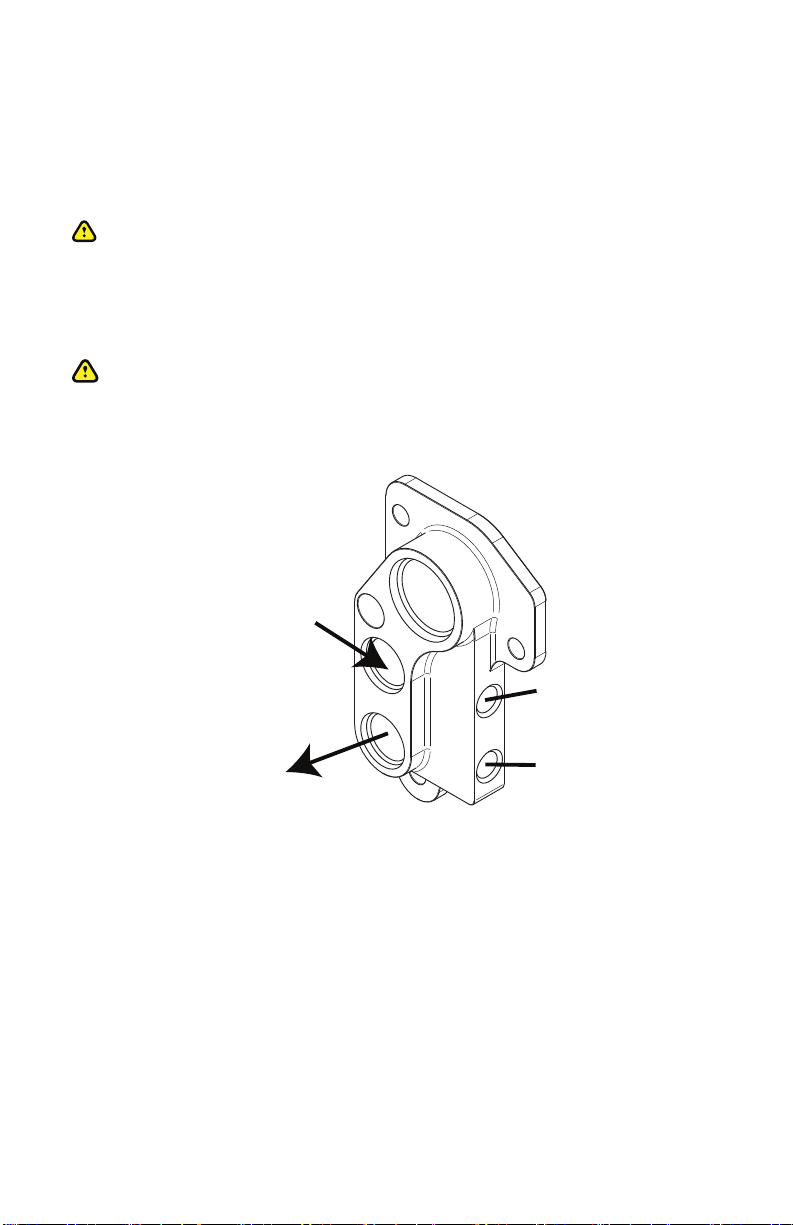
WARNING:Paycloseaenontotheoillineroung.Incorrectline
roungmayimpedeoilowtotheengine.
1. Note the port idencaon and direcons of ow illustrated in Figure
1.
OUT TO FILTER
CONNECT THIS PORT
TO THE INLET OF THE
OIL FILTER
IN FROM
FILTER / COOLER
CONNECT THIS PORT TO
THE OUTLET OF THE FILTER
OR OIL COOLER
PRE-FILTER SENSOR
PORT (1/4” NPT)
POST-FILTER SENSOR
PORT (1/4” NPT)
Figure1-PortDescripons
2. Wrap the male threads on the provided 90° 1/4 inch NPT adapter ng
with Teon tape three or four mes or apply Teon thread sealant.
3. Install the provided 90° 1/4”-18 NPT adapter ng into the sensor port
of EFR-100.
4.
Clean the threads on the factory pressure sensor. Wrap the threads
three to four mes with Teon tape or apply Teon thread sealant and
install into the provided 90° NPT adapter ng.
5.
Install the provided 1/4”-18 NPT plug into the second sensor port on

Visit www.improvedracing.com for addional support 5
EFR-100 if no other sensors are being used.
6. Install the coolant barb ng and oil cooler adapter ngs into EFR-
100. Torque the coolant barb ng to 30 lb- (41 N-m). Torque the oil
line adapter ngs to 20 lb- (27 N-m).
Tip: Lubricate the O-rings with engine oil to prevent O-ring damage.
7. Ensure that three O-rings are installed into the glands of EFR-100 prior
to installaon. HRG-1018 and HRG-1019 should be inserted into the
glands as shown in Figure 2.
HRG-1018
HRG-1019
Figure2-HRG-1018andHRG-1019O-RingPlacement
Tip: Lubricate the O-rings with engine oil to help retain them in the
glands during installaon.
8.
Using a 6 mm hex key, carefully install the EFR-100 onto the engine
block using the provided M8x1.25 socket screws.
UsecauonnottopinchordamagetheO-rings.
9. Torque all M8 socket screws to 18 lb- (24 N-m).
10.
Install the new silicone lower radiator hose and clamps, part number
EFR-800.
ApplicaonNote:See the next secon for radiator hose installaon for
the 1996-2004 SVT Cobra and Mach 1 Mustangs.
1996-2004 sVt cobra & MacH 1 Mustangs
only
Important:Perform these steps for the 1996-2004 SVT Cobra and Mach
1 Mustangs only. Skip this secon for all other vehicles.
1. SVT Cobra and Mach 1 Mustangs use an inline coolant thermostat on
the lower radiator hose. This requires cung the supplied radiator hose

Visit www.improvedracing.com for addi onal support
6
to t to the inline coolant thermostat housing. Cut the EFR-800 radiator
hose with a sharp razor or box cu er along the line shown in Figure 3
below. Only the right side of the hose will be used.
Figure3-ForfitmentonSVTCobraandMach1Mustangmodels,cutthesup-
pliedradiatorhosealongthelineshown.
2. Install the right end of the hose in Figure 3 onto the EFR-100 oil lter
adapter’s radiator hose barb and secure with the provided worm clamp.
3. A 1.75” to 1.50” hose reducer, part number RHR-175-150 (sold sepa-
rately) is required to connect the EFR-800 hose to the inline coolant
thermostat. Insert the reducer into the cut end of the hose and secure
to the inline thermostat with the included worm clamp.
installing tHe reMote oil Filter Pedestal
1. The recommended moun ng loca on for the remote lter pedestal is
the le side of the bumper bar, facing rearwards. An exis ng moun ng
hole in the bumper bar may be used so that only one addi onal hole
needs to be drilled.
2.
Secure the moun ng bracket to the lter pedestal and posi on it against

Visit www.improvedracing.com for addional support 7
the bumper bar with threaded backing plate and screws provided, as
shown in Figure 4.
3. Level the lter pedestal mark the unused hole locaon.
4. Remove the lter pedestal assembly from bumper bar.
5. Strike the hole center with a sharp punch.
6. Drill a hole into the bumper bar using a sharp, high-quality, cobalt steel
3/8” drill bit. The bumper bar is made from very hard steel and a good
cobalt steel drill bit is required to cut through it.
7. Reinstall the bracket and backing plate onto the bumper bar using two
screws from the lter pedestal hardware kit. Torque the screws to 24
lb- (33 N-m).
Figure4-RemoteFilterMountInstalledonFrontBumperBar
8.
Use the two plugs provided with the ENV-140 to plug the unused ports
as shown in Figure 5.
9. Connect the oil lines provided between the EFR-100 and ENV-140 as
shown in Figure 5.
a. Connect the 45-degree hose ends to the EFR-100.
b. Connect the 150-degree hose ends to the ENV-140. Note the
orientation of the hose end ttings in Figure 4.
WARNING: Ensure that the lines are connected correctly, or oil ow to
the engine will be blocked.

Visit www.improvedracing.com for addional support
8
IN
OUT
ENV-140
Figure5-OilLineRoungBetweenEFR-100andENV-140
10.
Lubricate the oil lter seal, pre-ll with engine oil, and install the oil lter
into the remote oil lter pedestal.
11. Trim the plasc fascia panel located on the front le side of the frame
rail as shown in Figure 6 to clear the oil lines.
Figure6-TrimmingtheFrontLeFasciaPanel
12. Use the provided zip-e to secure the oil lines to the exisng hole in
the frame rail, as shown in Figure 7.

Visit www.improvedracing.com for addional support 9
Figure7-SecuringtheOilLinestotheFrameRail
13. Reinstall the trimmed fascia panel, as shown in Figure 8. Note that the
oil lines now clear the fascia panel.
14. Install the hose separator provided in the hardware kit on the oil lines
near the engine block to keep the lines together. Ensure that the lines
are away from the front accessory drive pulleys.

Visit www.improvedracing.com for addional support
10
Figure8-TrimmedFasciaPanelInstalled
coMPleting tHe installation
1. Check that all lines and ngs are snug.
2. Check the engine oil level and add oil if necessary.
3.
Rell the engine’s coolant system using the manufacturer’s approved
method for your specic vehicle.
Tip: Consult the vehicle’s factory service manual for the correct coolant
specicaons and rell procedure.
4. Start the vehicle and inspect for oil and coolant leaks.
IMPORTANT:Checkthattheenginehasoilpressureimmediatelyaer
startup.Iftheoilpressureisabnormaloriftheenginemakesexcessive
noisethatdoesnotsubsidewithin3-5seconds,turnotheengine
immediatelyandchecktheoillineconneconsforroungerrorsora
kinked oil line.
5. Turn-o the vehicle, inspect the engine oil and coolant levels and add
oil or coolant as needed.
6. Reinstall the front bumper and all underbody panels. Lower the vehicle
back onto the ground.
7. Inspect lines and ngs for leaks aer one heat cycle. If any leaks are
detected, re-ghten the ngs unl the leak is eliminated.
Tabla de contenidos
Otros manuales de Accesorios para automóviles de Improved Racing

Improved Racing
Improved Racing EGM-502 Manual de usuario

Improved Racing
Improved Racing ENV-131-TX Manual de usuario

Improved Racing
Improved Racing FSM -RKIT Series Manual de usuario

Improved Racing
Improved Racing EGM-301 Manual de usuario

Improved Racing
Improved Racing EFR-600-TX Manual de usuario

Improved Racing
Improved Racing E5G-601 Manual de usuario

Improved Racing
Improved Racing E5G-600 Manual de usuario

Improved Racing
Improved Racing EGM-201 Manual de usuario


