HWAM 3630 Manual de usuario

01.11.2020 / 97-9664
www.hwam.com
3630 36503640 3660
Users manual EN

Table of contents
Drawings ...................................................3-6
HWAM Autopilot IHSTM .........................................7
Installation....................................................8
Firing manual - wood ..........................................13
Firing in general...............................................16
Maintenance .................................................17
Operational problems..........................................18
Declaration of Performance .....................................18
Product information EcoDesign ..................................19
Page 3 of 20 pages
A.
A1) A2)
1
2
3
4
34
1
B.
B2)
1
2
3
4
6
5
1
2
3
4
6
5
B1)

Page 4 of 20 pages
C.
1
2
3
5
4
6
6
7
8
9
11
12
10
C1) C2)
4
6
6
7
14
13
3
910
D1.
4
3
5
1
2
Page 5 of 20 pages
E. E1.

Page 6 of 20 pages
F.

Page 7 of 20 pages
HWAM® SMArtControl™
Congratulations on your new wood-burning stove complete with a HWAM®SmartControlTM
We are pleased that you have chosen a HWAM woodburning stove and confident that it will give you
much pleasure.
The HWAM®SmartControlTM is a digital control of the combustion in your new wood-burning stove.The
purpose of the HWAM®SmartControlTM is to control the combustion in an environmentally optimal and
economically efficient way, with a view to generating greater user comfort.
The HWAM®SmartControlTM is a new patented technology, which electronically adjusts the air supply to
the combustion chamber.Your new wood-burning stove continually measures the temperature and the
oxygen levels of the combustion. Moreover, it is programmed to supply oxygen to the fire through three
important air inlets in the right amount, and at the right time and place in the combustion chamber. By
downloading a free app for your smartphone or tablet, you can use the app among other things: to set
the thermostat to the desired room temperature level, choose time for night-time reduction and keep
your stove updated.The app also gives you current information on burning in the stove. See details in
separate manuals for the app IHS Smart ControlTM or in the Quickguide.
.
Your new wood-burning stove and the HWAM®SmartControlTM will ensure the cleanest possible com-
bustion as well as a good fuel economy, regardless of external conditions such as the type of firewood
used, the chimney, the user’s experience, and other external circumstances.
The HWAM®SmartControlTM consists of the following components:
• Air box: the Air box contains a printed circuit board/software, as well as three motors and dampers
that control primary, secondary, and tertiary combustion air.The fresh air system can be mounted
on the Air box to the back or in the bottom.
• Two sensors: a temperature sensor and an oxygen sensor transmit information from the wood-
burning stove to the Air box.
• Room temperature sensor: The room temperature sensor with batteries communicates with the
HWAM®SmartControlTM via a wireless connection. It should be placed so it does not have direct
radiant heat from the stove. Note that the maximum distance between stove and room temperature
indicator is about 4-5 metres.The range is reduced if there are walls or other obstructions between
the stove and the room temperature indicator.
• Electricity supply: from the Air box to the nearest wall socket.
• App "IHS Smart ControlTM:The app can be downloaded free from the App Store or Google Play
Store. See details in separate manuals for the app IHS Smart ControlTM or in the Quickguide.

Page 8 of 20 pages
InStAllAtIon
In general
To ensure optimum operation and safety,we recommend that the installation should be carried out by an
authorised HWAM retailer or a fitter recommended by the retailer.For an overview of HWAM retailers,
visit www.hwam.com under “Retailer locations”.
Safety
The installation of your HWAM woodburning stove must always comply with all European, national and
local building regulations.The installation must be carried out in accordance with the instructions in the
installation and user manuals and subsequently registered with the local authorities. Upon installation,
the chimney sweep must approve the installation before you can start using the woodburning stove.All
HWAM woodburning stove packaging material must be handled in accordance with local waste manage-
ment regulations.
Room requirements
Always ensure a supply of fresh combustion air to the room where the stove is to be installed. The
woodburning stove uses approx. 7-21 m3 of air per hour.A window that can be opened or an adjustable
air valve will be sufficient. It must not be possible to block the adjustable air valve/grate. In newly built/
airtight dwellings, we recommend that a fresh air system should be installed for the direct supply of
external air to the combustion.This fresh-air system may be bought separately.
Before installing the stove, you must ensure that the load-bearing capacity of the floor can withstand the
weight of the stove and the chimney. The weight of the chimney should be calculated according to its
dimensions and height. Remember to consider that the stove must be connected to power.
Technical measures and data
Test results from nominal test EN 13240
Nominal heating effect 6,0 kW
Flue gas temperature EN 13240 measurement point 269ºC
Flue gas temperature measured in the outlet socket 325ºC
Exhaust gas flow 5,04 g/s
Efficiency 80,7 %
Annual efficiency (EcoDesign) 70,7 %
PM 21 mg/m3
OGC 56 mg/m3
NOx 110 mg/m3
CO at 13% O21250 mg/m3
CO at 13% O20,10 %
Energy efficiency index 107
Energy efficiency class A+
Test result based on NS 3058
Particle emissions 1,78 g/kg
The declaration of performance (DoP) can be downloaded from our website, www.hwam.com.

Page 9 of 20 pages
Model Weight Height Width Depth
HWAM 3630c/3630m 139/136 kg 114,8 cm 55,6 cm 44,2 cm
HWAM 3640c/3640m 139/136 kg 114,8 cm 55,6 cm 44,2 cm
HWAM 3640c/3640m with natural stone cladding 211/208 kg 114,8 cm 60,0 cm 44,2 cm
HWAM 3640c/3640m with soapstone cladding 229/226 kg 114,8 cm 60,0 cm 44,2 cm
HWAM 3650c/3650m 171/168 kg 150,8 cm 55,6 cm 44,2 cm
HWAM 3660c/3660m 171/168 kg 150,8 cm 55,6 cm 44,2 cm
HWAM 3660c/3660m w/heat-storing stone 260/257 kg 150,8 cm 60,0 cm 44,2 cm
HWAM 3660c/3660m w/soapstone cover 282/279 kg 150,8 cm 60,0 cm 44,2 cm
Heat storage stones, HWAM 3650+3660 55 kg
Floor plate
European, national and local regulations must be observed in terms of the size and thickness of a non-
combustible floor covering the floor in front of the combustion chamber opening. Ask your HWAM
retailer for assistance.The combustion chamber opening is 36.7 cm wide.
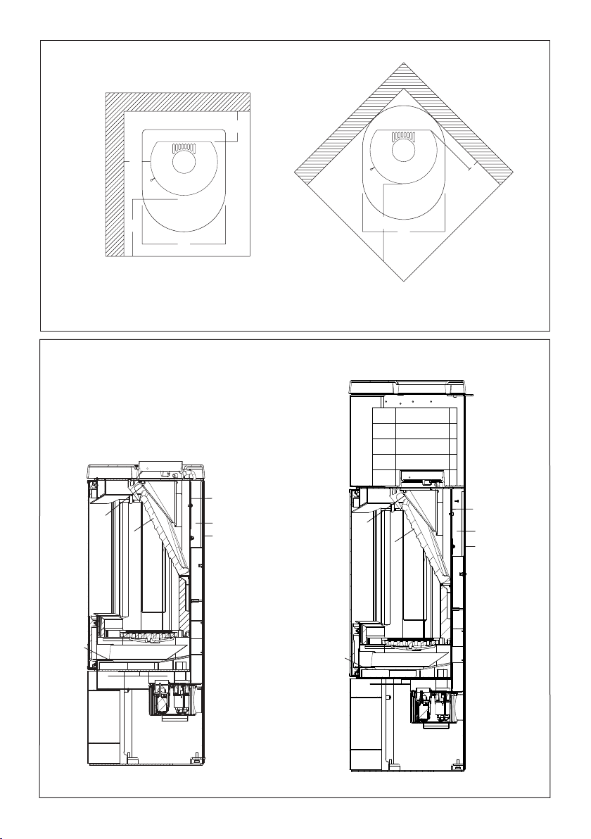
Distance to combustible materials
Min. distances - uninsulated flue gas pipe (drawing A) HWAM 3630
HWAM 3650
HWAM 3640
HWAM 3660
1. Recommended for brick wall, back, 10 cm 10 cm
2. Recommended for brick wall, side 15 cm 10 cm
1. For combustible back wall 10 cm 10 cm
2. For combustible side wall 40 cm 40 cm
1.To combustible wall,corner installation, 45º 35* cm 20* cm
3. Distance to furnishings in front, 90 cm 90 cm
*All dimensions in connection with corner installation are only recommendations. For UK: Please consult
a qualified and competent Installer for clarification.
Remember to pay attention to the applicable regulations concerning the required distance
between the wall and smoke pipe.
The distance to a brick wall is set to faciliate the servicing of the HWAM®SmartControl™.
Please be aware that not all glass parts are heat-resistant. For this reason, a glass wall should sometimes
be treated as a combustible wall, in which case we ask you to contact your local chimney sweep or glass
producer to hear at what distance the stove should be kept from glass.
Requirements for chimney and smoke pipe
The height of the chimney must ensure sufficient draught and prevent any smoke nuisance.As a general
rule, satisfactory draught conditions are achieved if the chimney is 4 m above the stove and at least 80
cm above the ridge. If the chimney is placed at side walls, the top of the chimney should always be higher
than the ridge or the tallest point of the roof.Always be aware of any national and/or local regulations
applying to thatched roofs and the location of the chimneys.
The stove requires a minimum draught of 12 Pa (measured at EN 13240 measurement point).If measured
just above the smoke flue socket, the chimney draught must be 18-20 Pa.
The chimney must have a minimum clearing of Ø 150 mm. The chimney must be provided with an
easily accessible cleaning door.The chimney and flue duct must be of flue class T400 and be CE marked.
Furthermore, it must have obtained the classification of G in soot fire testing.The required distance to
combustible material must be complied with in accordance with the brand label.Ask your HWAM retailer
for further information.

Page 10 of 20 pages
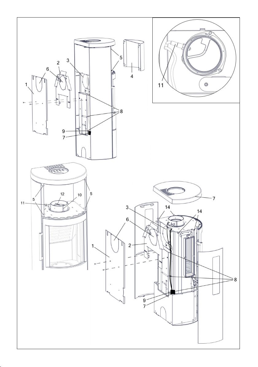
Changing the smoke outlet from top outlet to back outlet (HWAM 3630/3640 IHS)
(Drawing E)
1. Removing sides. Lift one side about 10 mm and pull it away from the stove so that it disengages from
the guide pins on the bottom plate of the stove. Repeat on the other side.
2. Removing the top plate (7). Remove the four screws (14) (Torx Bit no. 30 or M6 nut) beneath the top
plate, two on each side, and lift the top plate off.
3. Removing the rear plate (1). Remove the two screws in the middle of the rear plate. Lift the rear
plate and pull it away from the stove so that it disengages from the guide pins on the bottom plate of
the stove.There is a cut-out in the rear plate for the smoke outlet. Break off the plate (6) within this
cut-out to make a hole in the rear plate so there is room for the smoke outlet.
4. Remove the heat shield (2) by lifting it off the stove.The heat shield has a cut-out for the flue duct.
Break off the pre-cut plate (9); the resulting hole fits the flue duct.
5. Removing the cover plate (3). Remove the cover plate on the back of the stove by removing the three
screws (Torx Bit no. 30).
6. Open the metallic tabs (8) and take the wires out.
7. Pull the lambda sensor coupling (7) free of the wire fastener (9).
8. Remove the temperature monitor (12) from the smoke ring.
9. Installing a heat shield (2). Replace the heat shield at the back of the stove.
10.Removing the flue ring (10).To remove the flue ring (above the combustion chamber), unscrew the
three screws. Lift the flue ring off the top of the stove.
11.The temperature gauge (12) and the lambda sensor coupling (7) are pulled out from the left side of
the wood section and pushed in again through the hole in the right-hand side so that the wires are
kept on the left side of the stove when seen from behind.
12.Reattach the temperature monitor (12) in the smoke ring, leading the sensor about 3 cm into the
smoke ring.
13.Installing the cover plate (3). Place the cover plate over the hole (above the combustion chamber,
where the flue ring was just removed) and fasten with the three screws (Torx Bit no. 30).
14.Installing the flue ring (10). Insert the flue ring into the smoke outlet hole in the rear of the stove and
secure it with the three screws.NB: Remember to turn the lambda probe (11) as illustrated in drawing
E1.
15.Reposition the lambda sensor coupling (7) in the wire fastener (9).
16.Fix the two wires by closing the metallic tabs (8) again.
17.Installing the rear plate (1). Place the rear plate on the guide pins; then press it in towards the stove.
Lift the rear plate and press it lightly inwards until it engages with the guide pins.Fasten the two screws
in the middle of the rear plate again.
18.Installing the top plate of the stove (7). Place the top plate on the fittings and secure it with the four
screws (14), two on each side.
19.Installing sides. Put the sides on the guide pins in the bottom plate of the stove and press them in
towards the stove. Lift the sides and press them lightly inwards until they engage with the guide pins.
An accessory top cover is available to cover the hole in the stove top plate if the smoke outlet is connected
at the rear of the stove.
Changing the smoke outlet from top outlet to back outlet (HWAM 3650/3660 IHS)
(Drawing E)
1. Removing the rear plate (1). Remove the two screws in the middle of the rear plate. Lift the rear
plate and pull it away from the stove so that it disengages from the guide pins on the bottom plate of
the stove.There is a cut-out in the rear plate for the smoke outlet. Break off the plate (6) within this
cut-out to make a hole in the rear plate so there is room for the smoke outlet.
2. Remove the heat shield (2) by lifting it off the stove.The heat shield has a cut-out for the flue duct.
Break off the pre-cut plate (6); the resulting hole fits the flue duct.
3. Removing the cover plate (3). Remove the cover plate on the back of the stove by removing the three
Otros manuales para 3630
3
Este manual sirve para los siguientes modelos
3
Tabla de contenidos
Otros manuales de Calentador de HWAM


Manuales populares de Calentador de otras marcas


Empire Heating Systems
Empire Heating Systems WCC65 Manual de usuario

Wetekom
Wetekom 92 86 43 Manual de usuario

Desa
Desa SPC170-F Manual de usuario

Watlow
Watlow Watrod Electric Tubular Heaters Manual de usuario

Haverland
Haverland ECO-DRY GPS Series Manual de lista de piezas

Stelpro
Stelpro ASILVC2060 Series Manual de usuario