Holman 12004 Manual de usuario

Instructions –PRO Forklift Service Body Rack
For Technical Support Call: 800-343-7486, Monday-Friday, 7AM - 4 PM (PST) Page 1
PLEASE READ ALL INSTRUCTIONS AND WARNINGS PRIOR TO
ASSEMBLING, INSTALLING, AND USING THIS PRODUCT.
WARNING
Always check for wires, fuel tanks and lines, brake lines and other important
vehicle functionality items prior to drilling and installing all products.
Too much weight will greatly reduce the stability of your vehicle. Holman makes
no representation or warranty as to the amount of weight your vehicle can
safely carry. For guidance, we recommend that you consult the vehicle
manufacturer. At no time should the weight of the vehicle, rack, driver,
passengers and cargo loaded on a Holman rack exceed either the Gross
Vehicle Weight Ratio (GVWR) or the Gross Axle Weight Ratio (GAWR) as
specified by the vehicle manufacturer.
Do not use your rack with the rear cross bar removed. Removal of rear crossbar
will affect structural integrity of the rack.
Secure all payloads properly for safe transportation.
Tools Needed
1/2” 9/16”, 3/4” Box Wrenches
1/2”, 9/16”, 3/4” Sockets and Wrench
7/32”, 5/16” Allen Wrenches
Drill
11/32”, 13/32” Drill Bits
Drill Bit Stop Collar
Before You Begin
1. Read all instructions carefully, and follow each step in proper sequence, for ease and
speed in assembling your Holman rack.
2. The “bulkhead” is the panel at the front of the service body. Measure the distance from the
top of the bulkhead to the top of the truck’s cab. This distance should be in the range of
15” to 22”.
3. PROPER SEALANT APPLICATION IS CRITICAL TO PREVENTING WATER PENETRATION
INSIDE THE RACK. Apply a healthy bead of sealant entirely around every swaged joint and
every bolt going through tubing. Improper sealing can lead to water penetration and rust
on inside surfaces.

Instructions –PRO Forklift Service Body Rack
For Technical Support Call: 800-343-7486, Monday-Friday, 7AM - 4 PM (PST) Page 2
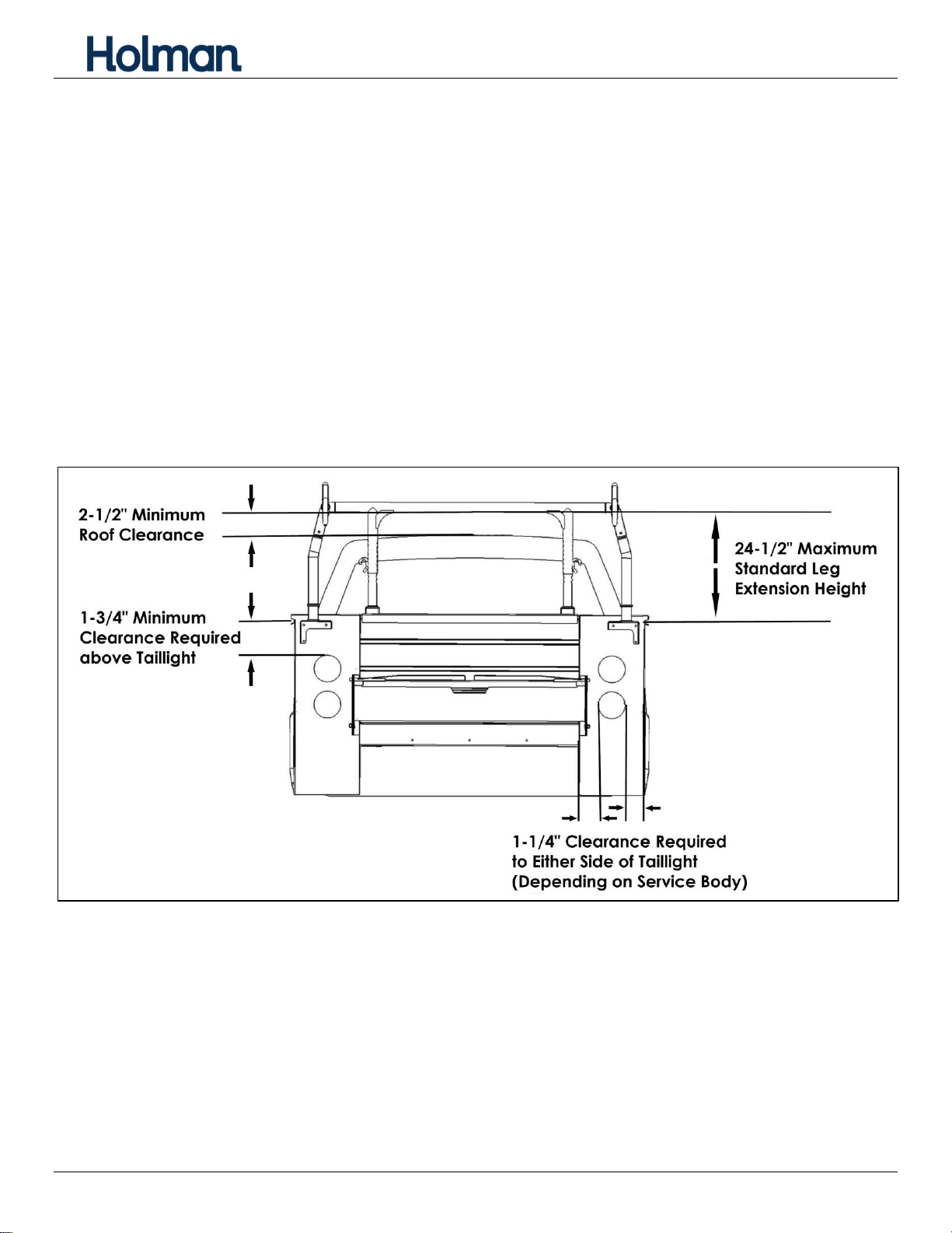
4. Standard mounting is on the rear panel. Check to ensure the rear panel of the service body
is free of taillights or other obstructions (inside or out) in the area where the rear legs of
the rack bolt to the body. Consult sketch below.
a. There must be open unobstructed space at least 1-3/4” above taillight and below flip
top box lid.
b. There must be open unobstructed space at least 1-1/4” to the left or right of taillight.
c. The distance between the crown of the roof plus 2-1/2” to the top of the mount bracket
must be no greater than 24-1/2”. If the distance is greater than 24-1/2”, the optional
9” extension kit (31520) is required.
d. The service body foot must be mounted as close as possible to the vertical exterior
corner of the rear body panel. If mounting to the vertical exterior corner of the rear
body panel is not possible, the right and left service body rear feet can be switched
and the feet can be mounted as close as possible to the vertical interior corner of the
rear body panel.

Instructions –PRO Forklift Service Body Rack
For Technical Support Call: 800-343-7486, Monday-Friday, 7AM - 4 PM (PST) Page 3

Instructions –PRO Forklift Service Body Rack
For Technical Support Call: 800-343-7486, Monday-Friday, 7AM - 4 PM (PST) Page 4
Table of Contents
Leg and Bar Kit Parts List................................................................................................................5
Hardware Kit....................................................................................................................................7
Hardware (Continued) .....................................................................................................................8
Sealant Application..........................................................................................................................9
Step 1 –Measure Service Body and Truck .....................................................................................9
Step 2 –Install Front Leg Angle Mount .........................................................................................10
Step 3 –Install Bulkhead Bracing..................................................................................................10
Step 4 –Assemble Front Leg Assembly........................................................................................11
Step 5 –Join Side Channels .........................................................................................................11
Step 6 –Attach Wind Deflector......................................................................................................12
Step 7 –Attach Front Tube............................................................................................................13
Step 8 –Attach Center Crossbar...................................................................................................13
Step 9 –Attach Rear Take-out Bar................................................................................................13
Step 10 –Attach Rear Legs...........................................................................................................14
Step 11 –Attach Front Legs..........................................................................................................14
Step 12 –Install Foot to Rack........................................................................................................16
Step 13 –Install Rack onto Service Body......................................................................................17
Step 14 –Install Support Arm........................................................................................................18
Step 15 –Tighten Hardware..........................................................................................................18
Troubleshooting.............................................................................................................................19
Rear Take-out Bar Position Lock...................................................................................................19
Adjust Wind Deflector....................................................................................................................19
Install Extra Crossbar ....................................................................................................................20

Instructions –PRO Forklift Service Body Rack
For Technical Support Call: 800-343-7486, Monday-Friday, 7AM - 4 PM (PST) Page 5
Leg and Bar Kit Parts List

Instructions –PRO Forklift Service Body Rack
For Technical Support Call: 800-343-7486, Monday-Friday, 7AM - 4 PM (PST) Page 6
Side Channel Parts List
* Extra crossbar is included in extended and crew cab kits only.
*

Instructions –PRO Forklift Service Body Rack
For Technical Support Call: 800-343-7486, Monday-Friday, 7AM - 4 PM (PST) Page 7
Hardware Kit

Instructions –PRO Forklift Service Body Rack
For Technical Support Call: 800-343-7486, Monday-Friday, 7AM - 4 PM (PST) Page 8
Hardware (Continued)

Instructions –PRO Forklift Service Body Rack
For Technical Support Call: 800-343-7486, Monday-Friday, 7AM - 4 PM (PST) Page 9
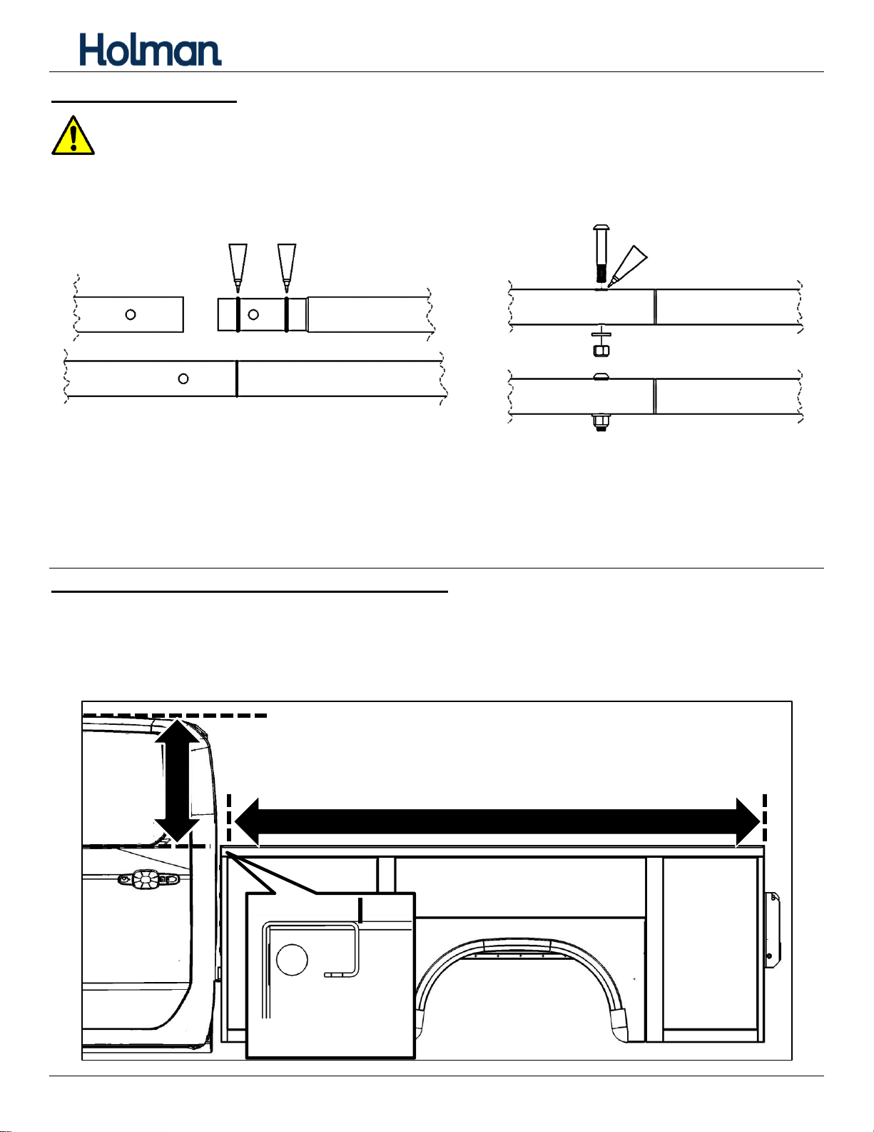
Sealant Application
Proper sealant application is critical to preventing water penetration inside the
rack.
Apply a healthy bead of sealant around every swaged joint as shown. Improper sealing can lead
to water penetration and rust on inside surfaces.
Wipe any excess sealant off immediately with a plastic scraper or paper towel. Any smeared
sealant can be rubbed off as soon as sealant dries.
Maintain this seal throughout the life of your rack.
Repeat process for opposite side.
Step 1 –Measure Service Body and Truck
Measure distance between inside of service body bulkhead to rear of service body.
Measure and record height from bulkhead to top of vehicle.
Crossbars will need to be 2-1/2” or more above the roof.
Cut way view of
bulkhead
MEASURE INSIDE DISTANCE BETWEEN BULKHEAD AND REAR PANEL
MEASURE
Este manual sirve para los siguientes modelos
1
Tabla de contenidos
Otros manuales de Accesorios para automóviles de Holman

Holman
Holman 3108SD Manual de usuario

Holman
Holman 31080C Manual de usuario

Holman
Holman 4A91H Manual

Holman
Holman 80160 Manual

Holman
Holman 40983 Manual

Holman
Holman 31110 Manual de usuario

Holman
Holman 31500 Manual de usuario

Holman
Holman 4A822 Manual

Holman
Holman 4A80L Manual de usuario

Holman
Holman 8012A Manual