Hardi HC 2500 Series Manual de usuario

CONTROLLER
HC2500 & HM1500
Instructionbook
679050- SW 1.52
GB - 07.2003
www.hardi-international.com

Illustrations, technical information and data in this book are to the best of our belief correct at
the time of printing. As it is HARDI INTERNATIONAL A/S policy permanently to improve our
products, we reserve the right to make changes in design, features, accessories, specifications
and maintenance instructions at any time and without notice.
HARDI INTERNATIONAL A/S is without any obligation in relation to implements purchased
before or after such changes.
HARDI INTERNATIONAL A/S cannot undertake any responsibility for possible omissions or inac-
curacies in this publication, although everything possible has been done to make it complete
and correct.
As this instruction book covers more models and features or equipment, which are available in
certain countries only, please pay attention to paragraphs dealing with precisely your model.
Published and printed by HARDI INTERNATIONAL A/S
We congratulate you for choosing a HARDI plant protection product.
The reliability and efficiency of this product depend upon your care.
The first step is to carefully read and pay attention to this instruction
book. It contains essential information for the efficient use and long
life of this quality product.

1
Content
Glossary and pictorials symbols............................................................................................2
Operator safety ................................................................................................................................3
Description.........................................................................................................................................3
Fitting the system .........................................................................................................................4
Power supply...........................................................................................................................6
Display .........................................................................................................................................7
Transducer pin and wire connections .....................................................................8
Speed transducer..................................................................................................................8
Flow transducer ....................................................................................................................9
Optional transducers.......................................................................................................10
Start-up..............................................................................................................................................11
Reading chosen volume rate .....................................................................................11
HM 1500: Changing the desired volume rate for alarm ............................11
HC 2500: Changing the volume rate.....................................................................11
Menus.................................................................................................................................................13
General keystroke ..............................................................................................................13
Keystroke menu tree chart .........................................................................................14
Main menu.............................................................................................................................15
Display readout...................................................................................................................16
Tank contents.......................................................................................................................17
Calibration..............................................................................................................................18
Alarms .......................................................................................................................................23
Sensor test..............................................................................................................................25
Area meter.......................................................................................................................................26
Mistblowers and HM 1500/HC 2500 ...............................................................................26
Storage...............................................................................................................................................27
Emergency operation...............................................................................................................27
Fault nding ..........................................................................................................................27
Technical specications...........................................................................................................30
Chart for recording values .....................................................................................................31
Extended menu............................................................................................................................31
EC Declaration of Conformity..............................................................................................33
Spare Parts .......................................................................................................................................34

2
We congratulate you for choosing a HARDI plant protection product. The reli-
ability and eciency of this product depend on your care.
Read and pay attention to this instruction book. It contains information for
the ecient use and long life of this quality product.
Glossary and pictorials symbols
HM 1500 HARDI Monitor 1500.
HC 2500 HARDI Controller 2500.
Transducer Device that transforms variations to a signal.
Also called a sensor.
[x] or [ y] Variable gures.
PPU Pulses per unit. For ow calibration.
The unit measure is litre.
UPP Unit per pulse. For speed calibration.
The unit measure is metre.
PPR Pulses per revolution. For revolutions calibration.
BK HARDI manual control unit.
BK/EC HARDI manual control unit (with electric on/o and
pressure regulation).
EVC or CB Electric control unit (without main valve).
NOTE: Text shown in square brackets or in the rectangular window will be
seen on the display.
E.g. [ MAIN MENU ]
M A I N M E N U
D i s p l a y readout
Operational problems
Technical specications
EC Declaration of Conformity
Description/Notes
Warning
Assembly
Winter storage
Operation/Use

3
Operator safety
Watch for the WARNING symbol . Your safety is involved so be alert!
Note the following recommended precautions and safe operating prac-
tices.
Read and understand this instruction book before using the equipment.
It is equally important that other operators of this equipment read and
understand this book.
Turn electrical power o before connecting and disconnecting the display
and transducers, servicing or using a battery charger.
If an arc welder is used on the equipment or anything connected to the
equipment, disconnect power leads before welding.
Test with clean water prior to lling with chemicals.
Keep children away from the equipment.
Do not use a high pressure cleaner to clean the electronic components.
Press the keys with the underside of your nger. Avoid using your nger-
nail.
If any portion of this instruction book remains unclear after reading it, con-
tact your HARDI dealer or HARDI service personnel for further explanation
before using the equipment.
Description
The HARDI Monitor 1500 and HARDI Controller 2500 are for use in agricultural
and horticultural production. HM 1500 is a monitor whereas HC 2500 permits
automatic control of application rate.
Main components are:
• Display
• Flow transducer
• Speed transducer
The matrix display has two lines permitting two lots of information to be
shown at the same time. Display readout includes dosage applied, speed, liq-
uid rate per minute, total covered area, total volume sprayed and 9 trip tellers
for area covered and volume sprayed. It is illuminated internally so readout is
possible even for night-time work.

4
Functions include correct area with closure of up to 8 spray boom sections,
alarm functions for dosage and minimum tank contents and possibility for
audio/visual alarm.
The transducers utilised are chosen for long service life and good signal quality.
Speed, area switch and revolutions transducer is the same component. The
ow transducer has a diode built into the housing to aid servicing. As the rotor
turns, the diode will ash thereby indicating it functions.
The system has a non-volatile memory with no battery which simplies stor-
age. All parameters in the menus are saved in the display’s memory and are
not lost when the power is disconnected.
The materials and electronics for the components have been developed to last
many years under agricultural conditions.
Options include a 4-20 mA transducer (e.g. pressure), revolutions transducer,
area meter transducer and switch box for boom sections when used with BK or
BK/EC control unit (only for HM 1500).
Fitting the system
Please note the conguration and connections for your system.
HM 1500 Monitor with manual control unit (BK, BK/EC)
The active boom width is always the total boom width.
The system can not automatically calculate correctly when one or more boom
sections are turned o.
1. HM 1500 display
2. Display connector plug
3. To 12 Volt power supply
4. Area switch (option)
5. Speed transducer
6. Flow transducer
7. Box connector socket

5
HM 1500 Monitor with manual control unit (BK, BK/EC)
and Spray box for boom sections
Active boom width is calculated automatically.
The Spray box switches are set to correspond with the boom sections.
NOTE: Extended menu setting:
[Control box ] is [ Connected ].
See “Extended menu”.
1. HM 1500 display
2. Display connector cable
3. To 12 Volt power supply
4. Area switch (option)
5. Speed transducer
6. Flow transducer
7. Box connector socket
8. Spray (control) box
HM 1500 Monitor with electric control unit
(EVC, CB)
Active boom width is calculated automatically when the boom sections are
operated.
NOTE: Extended menu setting:
[Control box ] is [ Connected ].
[ON/OFF valve ] is [ Not present ] for EVC and CB.
[Pressure system] is [No equalisation]
See “Extended menu”.
1. HM 1500 display
2. Display connector plug
3. To 12 Volt power supply
4. Area switch (option)
5. Speed transducer
6. Flow transducer
7. Box connector socket
8. Spray box for electric con-
trol unit
9. 39 pin plug to control unit
10. Electric control unit
6
T165-0002
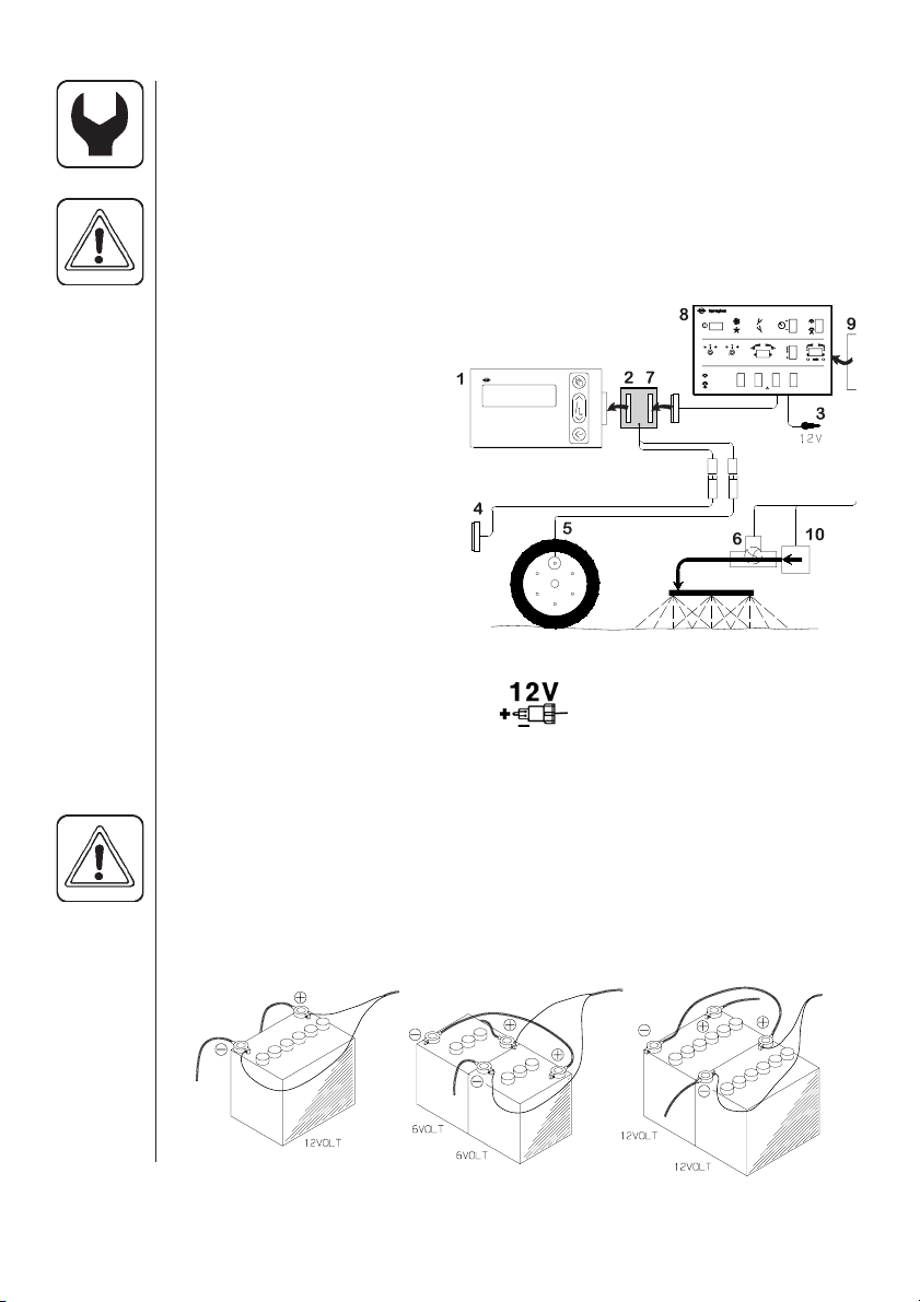
HC 2500 Controller with electric control unit
(EVC, CB)
Active boom width is calculated automatically when the boom sections are
operated.
NOTE: Extended menu setting:
[ON/OFF valve ] is [ Not present ] for EVC and CB.
[Pressure system] is [No equalisation]
See “Extended menu”.
1. HC 2500 display
2. Display connector cable
3. To 12 Volt power supply
4. Area switch (option)
5. Speed transducer
6. Flow transducer
7. Box connector socket
8. Spray box for electric con-
trol unit
9. 39 pin plug to control unit
10. Electric control unit
Power supply
The power supply is 12 Volt DC.
Brown wire is positive “ t”.
Blue wire is negative “ -”.
Power supply must come directly from the battery. The wires must have a
cross-sectional area of at least 1.0 mm2to ensure sucient power supply.
NOTE: Do not connect to the starter motor or generator/alternator. Warranty
is void if this is done.
Use the HARDI Electric distribution box (Ref. no. 817925) if the tractor has a
doubtful wiring.

7
B
A
C
B
D
A
A
C
C
Display
The display is tted in the tractor cabin
at a convenient place.
The mounting rod (A) is utilised to t
the display together with the Spray
box.
Place “ Quick guide”
sticker at C
NOTE: Power must be disconnected before
wire harness (B) is connected to the display.
The wire harness has identication labels
Dfor dierent connections. Connect up
specic to your version.

8
Transducer pin and wire connections
HARDI transducers colour codes
are as follows. Includes speed, ow,
area meter, revolutions and pres-
sure transducers.
Speed transducer for tractor
Note the following if the speed transducer is
tted to the tractor or vehicle.
The speed transducer is an inductive type. It
requires a metallic protrusion (e.g. bolt head)
to pass by it to trigger a signal. A diode on the
transducer will ash when a signal is detected.
Recommended distance between protrusion
and transducer is 3 to 5 mm.
Otros manuales para HC 2500 Series
1
Este manual sirve para los siguientes modelos
1
Tabla de contenidos
Otros manuales de Controladores de Hardi

Hardi
Hardi HC 9600 Manual de usuario

Hardi
Hardi HC5500 Manual de usuario

Hardi
Hardi HC 5500 SPRAY BOX III Manual de usuario

Hardi
Hardi HC5500 Manual de usuario

Hardi
Hardi HC 6500 Manual de usuario

Hardi
Hardi HC5500 Manual de usuario

Hardi
Hardi ISOBUS VT Manual de usuario

Hardi
Hardi COMMANDER 5500 Manual de usuario

Hardi
Hardi HC5500 Manual de usuario

Hardi
Hardi HC5500 Manual de usuario


