Goblin SPEED Manual de usuario


Goblin SPEED Manual
Release 1.0 -December 2013
SAB HELI DIVISION S.R.L.
Via San Crispino, 47
47030 San Mauro Pascoli (FC) - ITALY
7 – Assembling The Modules
8 – Installation of Swashplate Servos
9 – Installation of The Motor
10 – Installation of The ESC
11 – Installation of Flybarless Unit and RX
12 – Tail Assembly
1 – Serial Number
2 – Important Notes
3 – Components and Box
4 – Carbon frame Assembly
5 – Trasmission Assembly
6 – Main rotor
INDEX
13 – Installation of the Boom, Canopy
14 – Battery
15 – In flight
16 – Maintenance
17 – Exploded Views
18 – Spare Parts
//www.goblin-helicopter.com
http:
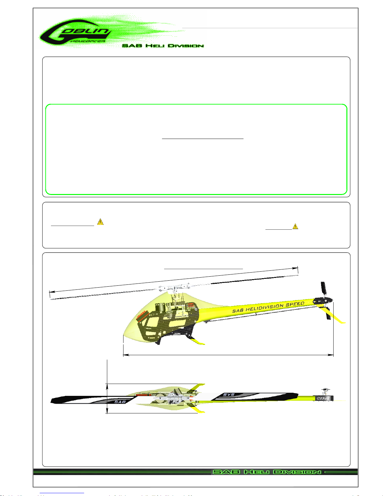
1626 mm
1320 mm
175 mm
Main rotor diameter: 1626mm (with 720mm blades)
Main blade length: up to 720mm
Tail rotor diameter: 283mm
Tail blade length: 104mm rouded tip ( up to 105mm)
Main shaft diameter: 12mm
Tail shaft diameter: 6mm
Spindle diameter: 10mm
Weight including standard electronics: 4010g (excluding batteries).
Motor size: Maximum 64mm diameter, maximum height 80mm.
Battery compartment: 75x58x350mm.
SPECIFICATIONS
It is extremely important that you take a moment to register your helicopter with us. This is the only way to ensure that you are
properly informed about changes to your kit, such as upgrades, retrofits and other important developments. SAB Heli Division cannot
be held responsible for issues arising with your model and will not provide support unless you register your serial number.
To mount the serial number tag on your helicopter, please refer to page 31.
Thank you for your purchase, we hope you enjoy your new Goblin helicopter!
SAB Heli Division
VERY IMPORTANT
Inside Box 5, you will find Bag 21. This bag contains your serial number tag. Please take a moment to register your kit online via
our web site at:
The Goblin Speed
is the best compromise between a 3D helicopter and a full body, aerodynamically efficient, speed helicopter.
The Goblin Speed incorporates all the best parts and components SAB Heli Division has to offer in order to support the most
extreme power systems available in the market today.
The kit combines incredible design features with good aerodynamic properties.
Please read this user manual carefully, it contains instructions for the correct assembly of the model.
Please refer to the web site www.goblin-helicopter.com for updates and other important information.
Copyright © 2013 - SAB Heli Division - All rights reserved
Page 1
Chapter 1, Serial Number

Use grease
(eg Tri-Flow
Synthetic Grease)
IMPORTANT NOTES
*This radio controlled helicopter is not a toy.
*This radio controlled helicopter can be very dangerous.
*This radio controlled helicopter is a technically complex device which has to be built and handled very carefully.
*This radio controlled helicopter must be built following these instructions. This manual provides the necessary information
to correctly assemble the model. It is necessary to carefully follow all the instructions.
*Inexperienced pilots must be monitored by expert pilots.
*All operators must wear safety glasses and take appropriate safety precautions.
*A radio controlled helicopter must only be used in open spaces without obstacles, and far enough from people to minimize
the possibility of accidents or of injury to property or persons.
*A radio controlled helicopter can behave in an unexpected manner, causing loss of control of the model, making it very
dangerous.
*Lack of care with assembly or maintenance can result in an unreliable and dangerous model.
*
Neither SAB Heli Division nor its agents have any control over the assembly, maintenance and use of this product.
Therefore, no responsibility can be traced back to the manufacturer. You hereby agree to release SAB Heli Division from
any responsibility or liability arising from the use of this product.
SAFETY GUIDELINES
*Fly only in areas dedicated to the use of model helicopters.
*Follow all control procedures for the radio frequency system.
*It is necessary that you know your radio system well. Check all functions of the transmitter before every flight.
*The blades of the model rotate at a very high speed; be aware of the danger they pose and the damage they may cause.
*Never fly in the vicinity of other people.
Indicates that for this
assembly phase you need
materials that are in
box xx, bag xx, tray xx.
NOTES FOR ASSEMBLY
P
lease refer to this manual for assembly instructions for this model.
Follow the order of assembly indicated. The instructions are divided into chapters, which are structured in a way that
each step is based on the work done in the previous step. Changing the order of assembly may result in additional or
unnecessary steps.
Use thread lockers and retaining compounds as indicated. In general, each bolt or screw that engages with a metal part
requires thread lock.
It is necessary to pay attention to the symbols listed below:
Important
Use CA Glue
Use retaining
compound
(eg Loctite 648)
Use retaining
compound
(eg Loctite 243)
Use grease
(eg Vaseline Grease)
Copyright © 2013 - SAB Heli Division - All rights reserved
Page 2
Chapter 2, Important Notes

ADDITIONAL COMPONENTS REQUIRED
*Electric Motor: 12S-520/650Kv, 14S-450/580Kv
Maximum diameter 64mm,
Maximum height 80mm,
Pinion shaft diameter 6/8mm
*Speed controller: minimum 160A to be safe
*Batteries: 12S-5000mAh or 14S-4500mAh
*1 flybarless 3 axis control unit
*Radio power system, if not integrated with the ESC
*3 cyclic servos
*1 tail rotor servo
*6 channel radio control system on 2.4 GHz
The assembly process is described in the following chapters.
Each chapter provides you with the box, bag and/or foam
tray numbers you will need for that chapter. The information
is printed in a green box in the upper right hand corner of the
page at the beginning of every chapter.
TOOLS, LUBRICANTS, ADHESIVES
*Generic pliers
*Hexagonal driver, size 1.5,2,2.5,3,4mm
*4mm T-Wrench
*5.5mm Socket wrench (for M3 nuts)
*8mm Hex fork wrench (for M5 nuts)
*Medium threadlocker (eg. Loctite 243)
*Strong retaining compound (eg. Loctite 648)
*Spray lubricant (eg. Try-Flow Oil)
*Synthetic grease (eg. Tri-Flow Synthetic Grease)
*Grease ( eg. Vaseline grease )
*Cyanoacrylate adhesive
*Pitch Gauge (for set-up)
*Soldering equipment (for motor wiring)
Inside the main box:
Box 2: Canopy, Blade Holder.
Box 3: Boom, Blades, Tail blades, Carbon rod.
Box 4: Mechanical parts in 4 trays:
Tray 1: Main rotor
Tray 2: Carbon frame and tail rotor
Tray 3: Transmission
Tray 4: Main structure
Box 5: Bags
Box 6: Carbon parts
Box 7: Carbon parts
Inside the main box there are:
Copyright © 2013 - SAB Heli Division - All rights reserved
Page 3
Chapter 3, Components and Box

4-Carbon Frame
The manufacturing process of the carbon parts
often leaves micro-burrs and sharp edges. We
recommend de-burring the edges to minimize
the risks of electrical wire cuts, etc. Very
important in red line zone.
Copyright © 2013 - SAB Heli Division - All rights reserved
Page 4
Chapter 4, Carbon Frame

Frame Spacer
(H0003-S)
......x10
Flat Head Cap Screw M2.5x5mm
Flat Head Cap Screw
M2.5x5mm
(HC128-S)
Stop Battery Plate
(H0150-S)
Socket Head Cap Screw
M2.5x8mm
(HC020-S)
Frame Spacer
(H0003-S)
Frame Spacer
(H0003-S)
Frame Spacer
(H0003-S)
Frame Spacer
(H0003-S)
ESC Support
(H0369-S)
ESC Support Assembly
Flat Head Cap Screw
M2.5x5mm
(HC128-S)
ESC Support
(H0153-S)
Flat Head Cap
Screw M2.5x5mm
(HC128-S)
Flat Head Cap Screw
M2.5x5mm
(HC128-S)
Battery Support Assembly
Flat Head Cap Screw
M2.5x5mm
(HC128-S)
Flat Head Cap Screw
M2.5x5mm
(HC128-S)
Flat Head Cap Screw
M2.5x5mm
(HC128-S)
Battery Tray
(H0002-S)
Socket Head Cap Screw M2.5x8mm
......x2
Note:
Copyright © 2013 - SAB Heli Division - All rights reserved
Page 5
Chapter 4, Carbon Frame

Socket Head Cap
Screw M3x10mm
(HC056-S)
Finishing Washer M3
(H0007-S)
Main Frame 1
(H0354-S)
......x3
Finishing Washer M3
......x5
Socket Head Cap
Screw M3x12mm
(HC62-S)
Socket Head Cap
Screw M3x10mm
(HC056-S)
Finishing
Washer M3
(H0007-S)
Flat Head Cap
Screw M3x8mm
(HC134-S)
Socket Head Cap Screw
M3x10mm
Flat Head Cap Screw
M3x8mm
......x1
Socket Head Cap Screw
M3x12mm
......x2
Note:
Landing Gear Support
(H0005-S)
Frame Spacer
(H0003-S)
Vertical ESC Support
(H0368-S)
Landing Gear Mount Speed
(H0374-S)
Right Main Frame Assembly
Right Main Frame Assembly
Battery Support
Assembly
Copyright © 2013 - SAB Heli Division - All rights reserved
Page 6
Chapter 4, Carbon Frame

Landing Gear
(H0375-S)
Flat Head Cap Screws M3x8mm
Flat Head Cap
Screws M3x8mm
(HC134-S)
Socket Head Cap
Screw M3x10mm
(HC056-S)
Finishing
Washer M3
..... x3
..... x3
Finishing Washer M3
Socket Head Cap Screw M3x10mm
..... x5
Canopy
Positioners
(H0159-S)
Main Frame
(H0354-S)
Vertical ESC Support
(H0368-S)
Socket Head Cap
Screw M3x10mm
(HC056-S)
Finishing
Washer M3
(H0007-S)
Socket Head Cap
Screw M3x10mm
(HC056-S)
..... x3
..... x1
Socket Head Cap
Screw M2.5x8mm
(HC020-S)
Finishing
Washer M2.5
(H0255-S)
Metrix Hex
Nylon Nut M2.5
(HC200-S)
H0370
..... x2
Socket Head Cap Screw M2.5x8mm
Finishing Washer M2.5
..... x2
Metrix Hex Nylon Nut M2.5
..... x2
Socket Head Cap
Screw M3x12mm
(HC062-S)
Socket Head Cap Screw M3x12mm
..... x2
Bottom Head Cap Screw M4x8mm
Bottom Head Cap
Screw M4x8mm
(HC098-S)
..... x4
Copyright © 2013 - SAB Heli Division - All rights reserved
Page 7
Chapter 4, Carbon Frame

5 - Transmission Assembly
Copyright © 2013 - SAB Heli Division - All rights reserved
Page 8
Chapter 5, Transmission Assembly
Tabla de contenidos
Otros manuales de Juguete de Goblin

Goblin
Goblin Urukay Competition Manual de usuario

Goblin
Goblin Goblin 770 Sport Manual de usuario

Goblin
Goblin SG651 Manual de usuario

Goblin
Goblin FIREBALL Manual de usuario

Goblin
Goblin 420 Manual de usuario

Goblin
Goblin urukay Manual de usuario

Goblin
Goblin 500S Manual de usuario

Goblin
Goblin Goblin Comet Manual de usuario

Goblin
Goblin 380 KYLE STACY EDITION Manual de usuario

Goblin
Goblin MINI COMET Manual de usuario


