Goblin Goblin Comet Manual de usuario


1490mm
340mm
240mm
Main rotor diameter: 1626mm (with 720mm Blades)
Tail rotor diameter: 282mm (with 105mm Tail Blades)
Motor size: Maximum 64mm diameter, maximum height 80mm.
Main Battery compartment: 2x 165x55x55mm.
SPECIFICATIONS
It is extremely important that you take a moment to register your helicopter with us. This is the only way to ensure that you are
properly informed about changes to your kit, such as upgrades, retrofits and other important developments. SAB Heli Division
cannot be held responsible for issues arising with your model and will not provide support unless you register your serial number.
The Serial number is also engraved in the Aluminum Top Plate.
Thank you for your purchase, we hope you enjoy your new Goblin helicopter!
SAB Heli Division
VERY IMPORTANT
In the Manual bag you will find a product card with your serial number. Please take a moment to register
your kit online via our web site at:
Please read this user manual carefully, it contains instructions for the correct assembly of the model.
Please refer to the web site www.goblin-helicopter.com for updates and other important information.
http:
//www.goblin-helicopter.com
12 – Installation of the FBL and Canopy
13 – Battery System
14 – In flight
15 – Maintenance
16 – Exploded Views
17 – Spare Parts
INDEX
1 – Serial Number
2 – Important Notes
3 – Components and Box
4 – Aluminum Frame and
Transmission Assembly
5 – Installation of Swashplate Servos
6 – Installation of The Motor
7 – Installation of The ESC
8 – Installation of Head System
9 – Main Module Completion
10 – Tail System
11 – Assembly of the Main Module
Page 1
Chapter 1, Serial Number

Use CA Glue
Use Proper
Lubricant
Indicates that for this
assembly phase you need
materials that are in Bag xx.
Bag xx
Use retaining
compound
(eg HA116-S)
Use retaining
compound
(eg HA115-S)
Important
NOTES FOR ASSEMBLY
Please refer to this manual for assembly instructions for this model.
Follow the order of assembly indicated. The instructions are divided into chapters, which are structured in a way that
each step is based on the work done in the previous step. Changing the order of assembly may result in additional or
unnecessary steps.
Use thread lockers and retaining compounds as indicated. In general, each bolt or screw that engages with a metal part
requires thread lock.
It is necessary to pay attention to the symbols listed below:
IMPORTANT NOTES
*This radio controlled helicopter is not a toy.
*This radio controlled helicopter can be very dangerous.
*This radio controlled helicopter is a technically complex device which has to be built and handled very carefully.
*This radio controlled helicopter must be built following these instructions. This manual provides the necessary information
to correctly assemble the model. It is necessary to carefully follow all the instructions.
*Inexperienced pilots must be monitored by expert pilots.
*All operators must wear safety glasses and take appropriate safety precautions.
*A radio controlled helicopter must only be used in open spaces without obstacles, and far enough from people to minimize
the possibility of accidents or of injury to property or persons.
*A radio controlled helicopter can behave in an unexpected manner, causing loss of control of the model, making it very
dangerous.
*Lack of care with assembly or maintenance can result in an unreliable and dangerous model.
*
Neither SAB Heli Division nor its agents have any control over the assembly, maintenance and use of this product.
Therefore, no responsibility can be traced back to the manufacturer. You hereby agree to release SAB Heli Division from
any responsibility or liability arising from the use of this product.
SAFETY GUIDELINES
*Fly only in areas dedicated to the use of model helicopters.
*Follow all control procedures for the radio frequency system.
*It is necessary that you know your radio system well. Check all functions of the transmitter before every flight.
*The blades of the model rotate at a very high speed; be aware of the danger they pose and the damage they may cause.
*Never fly in the vicinity of other people.
LIMITED WARRANTY.
SAB Heli Division reserves the right to change or modify this warranty without notice and disclaims all other warranties, express or implied.
(a)
This warranty is limited to the original Purchaser (“Purchaser”) and is not transferable. REPLACEMENT AS PROVIDED UNDER THIS WARRANTY
IS THE EXCLUSIVE REMEDY OF THE PURCHASER This warranty covers only those Products purchased from an authorized SAB Heli Division dealer.
Third party transactions are not covered by this warranty. Proof of purchase is required for warranty claims.
(b)
Limitations- SAB HELI DIVISION MAKES NO WARRANTY OR REPRESENTATION, EXPRESS OR IMPLIED, ABOUT NONIFRINGEMENT,
MERCHANTABILITY OR FITNESS FOR A PARTICULAR PURPOSE OF THE PRODUCT. THE PURCHASER ACKNOWLEDGES THAT THEY ALONE HAVE
DETERMINED THAT THE PRODUCT WILL SUITABLY MEET THE REQUIREMENTS OF THE PURCHASER’S INTENDED USE.
(c)
Purchaser Remedy- SAB Heli Division’s sole obligation hereunder shall be that SAB Heli Division will, at its option, replace any Product
determined by SAB Heli Division to be defective In the event of a defect, this is the Purchaser’s exclusive remedy. Replacement decisions are at
the sole discretion of SAB Heli Division. This warranty does not cover cosmetic damage or damage due to acts of God, accident, misuse, abuse,
negligence, commercial use, or modification of or to any part of the Product. This warranty does not cover damage due to improper installation,
operation, maintenance or attempted repair by anyone
DAMAGE LIMITS.
SAB HELI DIVISION SHALL NOT BE LIABLE FOR SPECIAL, INDIRECT OR CONSEQUENTIAL DAMAGES, LOSS OF PROFITS OR PRODUCTION OR
COMMERCIAL LOSS IN ANY WAY CONNECTED WITH THE PRODUCT, WHETHER SUCH CLAIM IS BASED IN CONTRACT, WARRANTY, NEGLIGENCE,
OR STRICT LIABILITY. Further, in no event shall the liability of SAB Heli Division exceed the individual price of the Product on which liability is
asserted. As SAB Heli Division has no control over use, setup, final assembly, modification or misuse, no liability shall be assumed nor accepted
for any resulting damage or injury. By the act of use, setup or assembly the user accepts all resulting liability. If you as the Purchaser or user are
not prepared to accept the liability associated with the use of this Product, you are advised to return this Product immediately in new and
unused condition to the place of purchase.
Page 2
Chapter 2, Important Notes

ADDITIONAL COMPONENTS REQUIRED
*Electric Motor: 12S – 480/600Kv, 14S – 450/560Kv
Maximum diameter 64mm,
Maximum height 80mm,
Pinion shaft diameter 8mm
*Speed controller: minimum 160A but in according with setup
*Batteries: 12S – 5000/5500mAh, 12S – 4300/5000mAh
*1 flybarless 3 axis control unit
*Separate radio power system: 2S Lipo 2500 mAh
*3 cyclic servos
*1 tail rotor servo
*6 channel radio control system on 2.4 GHz
(See configuration examples on page 8)
The assembly process is described in the following chapters.
Each chapter provides you with the box, bag and/or foam
tray numbers you will need for that chapter. The information
is printed in a green box in the upper right hand corner of the
page at the beginning of every chapter.
TOOLS, LUBRICANTS, ADHESIVES
*Generic pliers
*Hexagonal driver, size 1.5, 2, 2.5, 3, 4, 5mm
*4mm T-Wrench
*5.5mm Socket wrench (for M3 nuts)
*8mm Hex fork wrench (for M5 nuts)
*Medium threadlocker (eg. Thread Locker Medium
Strength HA116-S)
*Strong retaining compound (eg. Retaining Compound High
Strength Bonding HA115-S)
*Spray lubricant (eg. Try-Flow Oil)
*Synthetic grease (eg. Tri-Flow Synthetic Grease)
*Grease ( eg. Vaseline grease )
*Cyanoacrylate adhesive
*Pitch Gauge (for set-up)
*Soldering equipment (for motor wiring)
Inside the main box:
Box 2: Canopy, Landing gear, Top Fin, Botton Fin,
Motor Cover.
Box 3: Boom, Blades, Tail blades, Carbon rod,
Carbon Part.
Box 4: Mechanical parts in 4 trays:
Tray 1: Head System.
Tray 2: Transmission
Tray 3: Aluminum Main Frame
Tray 4: Tail System and Battery System
Box 5: Bags
Inside the main box there are:
Tray 1
Tray 2
Tray 3
MAIN BOX
BOX 2
BOX 4 BOX 5
BOX 3
Tray 4
Page 3
Chapter 3, Components and Box
BAG 1, Foam 3
Left Main Frame Assembly
Servo Support SR
(H0603-S)
Use Thread lock
on all Screws
Note:
Frame Spacer
(H0609-S)
ESC Support
(H0610-S)
Single Servo Support
(H0748-S)
Side Case SL
(H0605-S)
Socket Head Cap
Screw M2.5x8mm
(HC020-S)
Socket Head Cap
Screw M3x6mm
(HC044-S)
Button Head Cap
Screw M4x8mm
(HC098-S)
Socket Head Cap
Screw M3x8mm
(HC050-S)
Socket Head Cap
Screw M2.5x8mm
(HC020-S)
Note:
Socket Head Cap
Screw M3x8mm
(HC050-S)
Socket Head Cap
Screw M3x8mm
(HC050-S)
Socket Head Cap
Screw M3x8mm
(HC050-S)
Ball Bearing
12x
24 x 6mm
(HC426-S)
Left Main Frame
Assembly
Ball Bearing
10x
22 x 6mm
(HC479-S)
Ball Bearing
12x
28 x 7mm
(HC480-S)
Note:
Use
Retaining Compound
on all Bearing
Main Support SR
(H0606BM-S)
Top Plate SR
(H0607BM-S)
Rubber
[H0876]
Double
Side Tape
Use Thread lock
on all Screws
Page 4
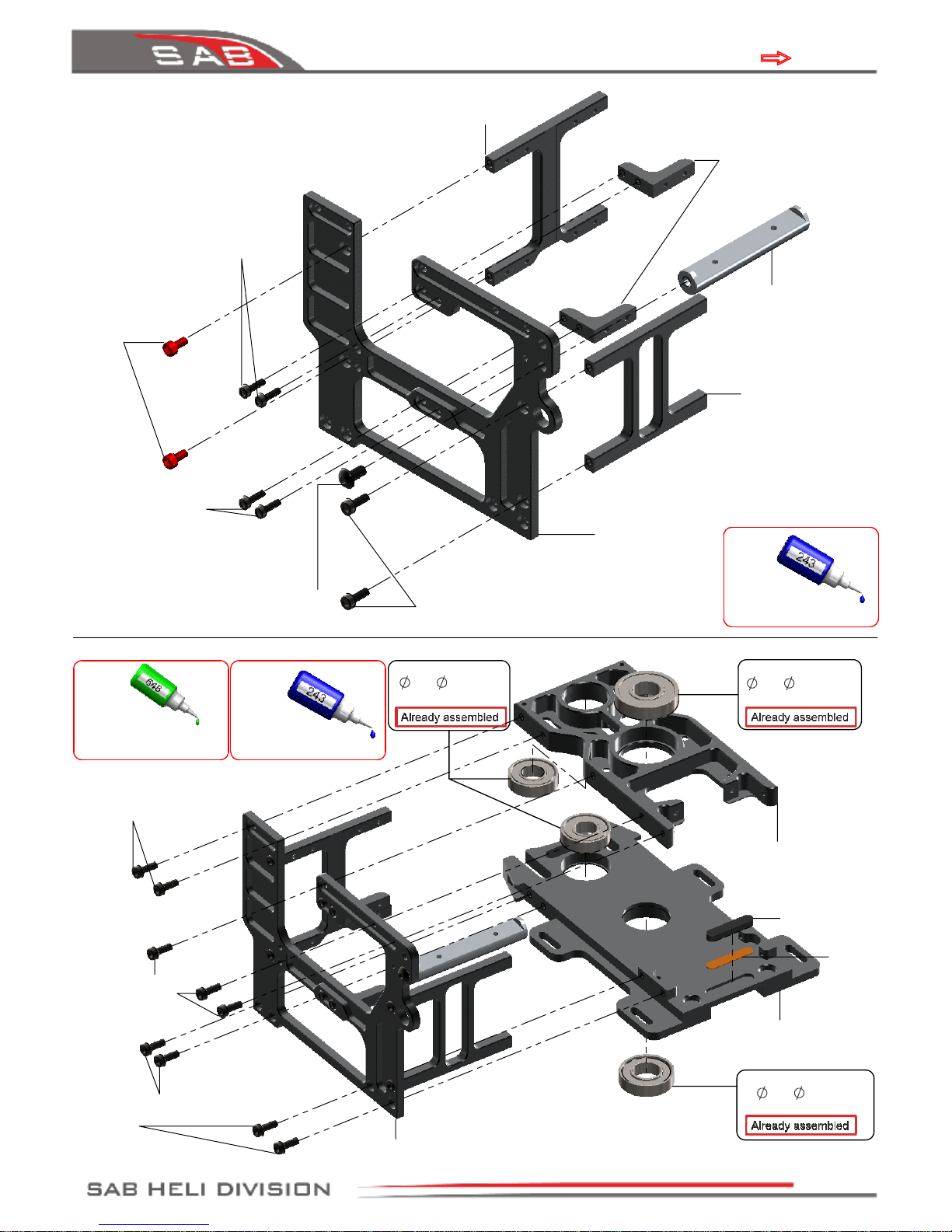
Chapter 4, Aluminum Frame and Transmission

Foam 1,2,3 , BAG 1
Right Main Frame Assembly
Socket Head Cap
Screw M3x8mm
(HC050-S)
Socket Head Cap
Screw M4x22mm
(HC104-S)
Botton Head Cap
Screw M4x8mm
(HC096-S)
Socket Head Cap
Screw M3x8mm
(HC050-S)
Note:
Use Thread lock
on all Screws
Side Case SR
(H0604-S)
Metric Hex
Nylon Nut M3
(HC206-S)
Metric Hex
Nylon Nut M4
(HC212-S)
Socket Head Cap
Shouldered M3x19mm
(HC079-S)
19T Drive Pinion
(H0156-S)
Metric Hex
Nylon Nut M4
(HC212-S)
M4 Locking Collar
(H0121-S)
Socket Head Cap
Shouldered M4x24mm
(HC111-S)
Note:
When you tighten the collar (
H0121-S
) on the main
shaft, ensure there is no axial play.
Push down the main shaft while pulling up the
locking collar. Tighten the screw
M4x22
at this time.
It is very important to lubricate these two
elements with a lubricant
(TRI-FLOW® synthetic grease or similar)
Main Shaft
(H0601-S)
Secondary Shaft
(H0602-S)
eg: Microlube GL261
Battery Stop
(H0736-S)
Swash plate
Anti-Rotation Guide
(H0756-S)
Socket Head Cap
Screw M3x8mm
(HC050-S)
Finishing
Washer M3
(H0007-S)
Main Gear
(H0320-S)
Note: Wide area here.
Socket Head Cap
Screw M3x8mm
(HC050-S)
Socket Head Cap
Screw M3x6mm
(HC044-S)
Page 5
Chapter 4, Aluminum Frame and Transmission

6.25
4.8
Main Frame
Assembly
60T Pulley
(H0171-S)
60T Pulley Assembly
(H0171-S)
Socket Head Cap
Screw M2x10mm
(HC010-S)
Front Tail Pulley Assembly
(H0172-S)
Bushing One Way
(H0891-S)
Use it for reduce the play if need
Note:
Correct insertion of
the one-way pulley
37T Pulley
(H0172-S)
Washer
10x
16x0.2mm
(HC232-S)
Metric Hex
Nylon Nut M2.5
(HC200-S)
BAG 1, Foam 2
One Way Beaing Oil
eg: HUDY One Way Oil
Bearing
10x
15x4mm
(HC420-S)
60T Pulley Assembly
(H0171-S)
One Way Bearing
10x
14x12mm
(HC442-S)
One Way Bearing
10x
14x12mm
(HC442-S)
Bearing
10x
15x4mm
(HC420-S)
Front Tail Pulley
Assembly
(H0172-S)
Socket Head Cap Screw
Shouldered M2.5x19mm
(HC033-S)
Bushing One Way
(H0891-S)
Page 6
Chapter 4, Aluminum Frame and Transmission

Uniball Spacer
[H0031]
(H0064-S)
120°
120°
Servo 2
Servo 3
Servo 1
A
DETAIL A
Socket Head Cap
Screw M3x6mm
(HC044-S)
Socket Head Cap
Screw M2.5x10mm
(HC022-S)
Servo Spacer
(H0075-S)
17-19mm
BAG 2
INSTALLATION OF SWASHPLATE SERVOS
The linkage ball must be positioned between
17-19 mm
out on the servo arm (F
igure 1
).
We recommend
metal servo horn
the 120° placement of the servos inside Goblin means the arms are difficult to access.
For this reason it is advisable to ensure alignment of the servo arms (and sub trim set) before installation
of the servos in the model. Proceed with installation following the instructions below.
SERVO ASSEMBLY 1, 2, 3
Uniball M2
5H6
(H0064-S)
Socket Head Cap Screw M2x8mm
(HC008-S)
or
Socket Head Cap Screw M2x6mm
(HC004-S) without Uniball Spacer
FRONT
Servo 1
Servo 3
Servo Spacer
(H0075-S)
Socket Head Cap
Screw M2.5x10mm
(HC022-S)
Socket Head Cap
Screw M2.5x10mm
(HC022-S)
ASSEMBLY OF THE BALL ON THE HORN.
The rods going from the servos to the swash plate must be as
vertical as possible. Not all servos are equal, so to better align
them you can choose to use the supplied spacer H0031.
Figure 2
illustrates this.
Servo Spacer
(H0075-S)
SERVO ASSEMBLY
Servo Spacer
(H0075-S)
Servo Spacer
(H0075-S)
Servo 2
Use Thread lock
on all Screws
Note 1
Note 2:
Please follow the following
figures for servo wire positioning.
Page 7
Chapter 5, Installation Of Swashplate Servos

Some example configurations:
CHOICE OF THE MOTOR PULLEY
It is important to choose the right reduction ratio to maximize efficiency based on your required
flight performance.
It is recommended to use wiring and connectors appropriate for the currents generated in a
helicopter of this class.
If you are using a head speed calculator which requires a main gear and pinion tooth count, use
214
teeth for the main gear (this takes into account the two stage reduction) and the tooth count of your
pulley as the pinion count.
Below is a list of available reduction ratios
:
H0175-18-S - 18T Pinion = ratio 11.9:1 H0175-22-S - 22T Pinion = ratio 9.8:1
H0175-19-S - 19T Pinion = ratio 11.3:1 H0175-23-S - 23T Pinion = ratio 9.3:1
H0175-20-S - 20T Pinion = ratio 10.7:1 H0175-24-S - 24T Pinion = ratio 8.9:1
H0175-21-S - 21T Pinion = ratio 10.2:1 H0175-25-S - 25T Pinion = ratio 8.6:1
GOBLIN COMET CONFIGURATIONS
Sport and Acrobatic Flight
Speed Flight
The high RPM flight condition should only be used while away from the pilot ( at least 30 meters).
Speed passes should always be made longitudinally to the pilot and spectators and always at a safe distance.
*
Rev:01
Battery
Motor
Motor Pulley
RPM Max
Pitch
12S
5000/5800 mAh
Kontronik Pyro 850-500
Scorpion HK-4535-500KV
23 2200 13
24 2280 13
25 2350 13
Xnova 4535-520KV
22 2150 13
23 2250 13
24 2300 13
14S
4300/5000 mAh
Kontronik Pyro 850-500
Scorpion HK-4535-500KV
20 2150 13
21 2250 13
22 2350 13
Xnova 4535-520KV
19 2150 13
20 2250 13
21 2350 13
14S
4300/5000 mAh
Kontronik Pyro 850-500
Scorpion HK-4535-500KV
22
2400 *
-10 / +16
23
2500 *
-10 / +16
24
2600 *
-10 / +16
Xnova 4535-520KV
21
2400 *
-10 / +16
22
2500 *
-10 / +16
23
2600 *
-10 / +16
Kontronik Pyro 1000-480
23
2400 *
-10 / +16
24
2500 *
-10 / +16
25
2600 *
-10 / +16
Xnova 50xx-535KV
Scorpion HK-5040-530KV
22
2550 *
-10 / +16
23
2650 *
-10 / +16
24
2750 *
-10 / +16
Page 8
Chapter 6, Installation Of The Motor

22mm
6mm
34mm
24mm
Set Screw
M4x6mm
(HC153-S)
Button Head Cap
Screw M4x8mm
(HC098-S)
21T Pulley
(H0175-21-S)
(See page 8 for optional
pulley selection).
Spring
[HC310]
(HC315-S)
Note for motor shaft
Additionally, ensure that the motor shaft
has an appropriate 'flat' to secure the set
screw of the motor.
Bushing
6x
8x18
(H0176-S)
Set Screw M5x20mm
(HC158-S)
Motor
Foam 2 , BAG 3
Motor Mount
(H0735-S)
Tail Belt Idler Assembly ...x2
(H0740-S)
Flanged Bearing
3x
7x3mm
(HC402-S)
Tail Belt Idler
[H0069]
Flanged Bearing
3x
7x3mm
(HC402-S)
Washer
5.3x
15x1mm
(HC188-S)
Metric Hex Nylon
Nut M5
(HC218-S)
Socket Head Cap
Screw M3x8mm
(HC050-S)
Column tensioner
(H0740-S)
Tail Belt Idler
Assembly
Socket Head Cap
Screw M3x12mm
(HC062-S)
Note:
An 8mm motor
shaft is recommended.
In cases of motors with
a 6mm motor shaft use
the supplied bushing.
Wires Orientation
Page 9
Chapter 6, Installation of The Motor
Tabla de contenidos
Otros manuales de Juguete de Goblin

Goblin
Goblin MINI COMET Manual de usuario

Goblin
Goblin Goblin 770 Sport Manual de usuario

Goblin
Goblin SPEED Manual de usuario

Goblin
Goblin Urukay Competition Manual de usuario

Goblin
Goblin 420 Manual de usuario

Goblin
Goblin FIREBALL Manual de usuario

Goblin
Goblin urukay Manual de usuario

Goblin
Goblin 500S Manual de usuario

Goblin
Goblin SG651 Manual de usuario

Goblin
Goblin 380 KYLE STACY EDITION Manual de usuario


