Forte F24DWS650PR Manual de usuario

Installation Manual
DISHWASHER
Built-In Dishwasher
F24DWS650PR

IMPORTANT SAFETY INSTRUCTIONS
BEFORE YOU BEGIN
Read these instructions completely and carefully.
IMPORTANT
•Observe all governing codes and ordinances.
•Note to Installer – Be sure to leave these instructions for the consumer’s and local inspector’s use.
•Note to Consumer – Keep these instructions with your User Guide for future reference.
•Skill Level – Installation of this dishwasher requires basic mechanical and electrical skills. Proper installation is the
responsibility of the installer. Product failure due to improper installation is not covered under the appliance
warranty.
•Completion Time – One to three hours. New installations require more time than replacement installations.
IMPORTANT
•The dishwasher MUST be installed to allow for future removal from the enclosure if service is required.
•If you received a damaged dishwasher, you should immediately call .customer service
FOR YOUR SAFETY
Read and observe all CAUTIONS and WARNINGS shown throughout these instructions. While performing installations
described in this booklet, gloves and safety glasses or goggles should be worn.
Warning
This dishwasher comes with a heating element to heat the water. To avoid the risk of a serious burn, don't touch the
heating element when the dishwasher is on.
CAUTION
RISK OF ELECTRIC SHOCK
DO NOT OPEN
This symbol indicates that dangerous voltage constituting a risk of
electric shock is present within your refrigerator.
This symbol indicates that there are important operating and
maintenance instructions in the literature accompanying your
refrigerator.
WARNING: To reduce the risk of electrical shock, fire, or injury to persons, the installer must ensure that the dishwasher is
completely enclosed at the time of installation.
2

READ CAREFULLY.
KEEP THESE INSTRUCTIONS.
If you have an installation problem, contact your dealer or installer. You are responsible for providing adequate electrical,
exhausting, and other connecting facilities.
Preparing to install your dishwasher
Parts supplied:
Tools needed:
Hose clamp Drain hose
Phillips screwdriver
Adjustable wrench
Flashlight
1/4 in. and 5/16 in.
Nut driver
Carpenters
square
Tubing cutter
Bucket
Safety glasses
Measuring tape
Hole saw
set Drill and bits
Gloves
New installations only
Level
Top mounting clips (2)
Screws A
ST4 x 20 (4)
Screws D
ST3.5 x 45 (4)
Screws C
ST3.5 x 25 (2)
Screws B
ST4 x 14 (8)
Brackets (2) Top Hook
Mounting Seats (2)
3

Enclosure requirements
•The dishwasher must be installed so that the drain hose is no more than 10 feet (3.01 m) in length, for proper drainage.
•This dishwasher is designed to be enclosed on the top and on both sides by a standard residential kitchen cabinet unit.
•The installation enclosure must be clean and free of any obstructions.
•The enclosure must be at least 24 inches (61 cm) wide, 25 inches (63.5 cm) deep, and 34 inches (86.4 cm) high.
•For the front door of the dishwasher to be flush with the front edge of the counter top, the counter top must be 25
inches (63.5 cm) deep.
Materials needed (kit purchased separately):
90° Elbow, ferrule and compression nut. (3/8
NPT external thread on one end. Other end
sized to fit water supply line
Three wire nuts (UL listed)
(two included in kit)
Teflon thread
seal tape
Air gap (if
required)
Hand shut-off
valve
Screw-type hose clamps
Strain relief (for
electrical
connections)
Electrical cable or power
cord (See Electrical
Requirements section)
Hot water line (min.
3/8 in. copper) kit
Waste tee for
house plumbing
(if applicable) Coupler for extending
drain line (if applicable)
New installations only
Gardenhose
connection
“T” connection
Not included in kit
34” (86.4cm)
min.
24” (61 cm)
min.
25” (63.5 cm)
min.
4

If installing into a corner, allow 2 in. (5.08 cm) min. clearance between dishwasher and adjacent cabinet, wall, or other
appliances. Allow 25.63 in. (65.1 cm) min. clearance from the front of the dishwasher for opening the door.
Drain requirements
•Follow all local codes and ordinances.
•Do not exceed 10 ft. (3.01 m) of drain hose.
•Do not connect the drain lines from other devices to the dishwasher drain hose.
•The dishwasher must be connected to a waste line with an air gap (not provided) or a 32 in. (81.28 cm) high (min.) drain
loop, depending on local codes and ordinances, to prevent back flow into the dishwasher.
•An air gap must be used if the waste tee or garbage disposal connection is less than 18 in. (45.72 cm) above the floor, to
prevent siphoning.
Drain preparation
The type of drain installation required depends on the answers to the following questions:
•Do local codes or ordinances require an air gap?
•Will the waste tee or garbage disposal connection be less than 18 in. (45.72 cm) above the floor?
•Will installation have a drain loop less than 32 in. (81.28 cm) above the floor?
If the answer to ANY of these questions is YES, Method 1 MUST be used. Otherwise, either Method 1 or
Method 2 may be used.
Install the waste tee or garbage disposal connection and air gap according to manufacturer’s instructions.
Caution:
•An air gap MUST BE USED if the drain hose is connected to a waste tee or garbage disposal lower than 18 in. (45.72 cm) above the
floor.
•Failure to provide the proper drain connection height with an air gap or 32 in. (81.28 cm) (min.) high drain loop will result in
improper draining of the dishwasher.
Clearance for door opening
2” (5.08 cm) min.
Dishwasher
Countertop
25.63”(65.1 cm)
5

Method 1 - Air gap with a waste tee or garbage disposal connection
Method 2 - High drain with a waste tee or garbage disposal connection
You must provide a method to attach the drain hose to the underside of the countertop.
Electrical requirements
•This appliance must be supplied with 120V, 60 Hz, and it must be connected to its own, properly grounded branch
circuit that is protected by a 15 or 20 ampere circuit breaker or time delay fuse.
•Wiring must be two wire with ground.
•If the electrical supply does not meet the above requirements, call a licensed electrician before proceeding.
GROUNDING INSTRUCTIONS
Grounding Instructions – Cable Direct
This appliance must be connected to a grounded metal, permanent wiring system, or an equipment grounding conductor
must be run with the circuit conductors and be connected to the equipment grounding terminal or lead on the appliance.
Grounding Instructions – Power Cord Models
This appliance must be grounded. In the event of a malfunction or breakdown, grounding will reduce the risk of electrical
shock by providing a path of least resistance for electric current. The plug must be plugged into an appropriate outlet that
is installed and grounded in accordance with local codes and ordinances.
WARNING
The improper connection of the equipment grounding conductor can result in a risk of electric shock. Check
with a qualified electrician or service representative if you are in doubt that the appliance is properly
grounded.
Direct Wire Method
•The cable must be routed as shown in Cabinet preparation and wire routing on page 8, and extend a minimum of 24 in.
(60.96 cm) from the rear wall.
•Use flexible, armored, or nonmetallic sheathed, copper wire with grounding wire that meets the wiring requirements
for your home and local codes and ordinances.
•Use a UL Listed/CSA Approved strain relief.
Warning: Remove the house fuse or open the circuit breaker before beginning the installation. Do not use an extension
cord or adapter plug with this appliance.
18 in. (45.72 cm)
32 in. (81.28 cm) (min.)
18 in. (45.72 cm)
32 in. (81.28 cm) (min.)
6
Power Cord Method
•Install a 3-prong grounding type receptacle. The wall outlet can be installed in a cabinet or on a wall adjacent to the
undercounter space in which the dishwasher is to be installed.
•Use power cord kit (part number 5304504505) under Smart Choice brand marked with Dishwasher Install Kit With
Power Cord, available for purchase from an authorized store. The power cord and connections must comply with local
codes and ordinances.
•The recommended power cord length is 54 in. (1.4 m) min. and 64 in. (1.6 m) max.
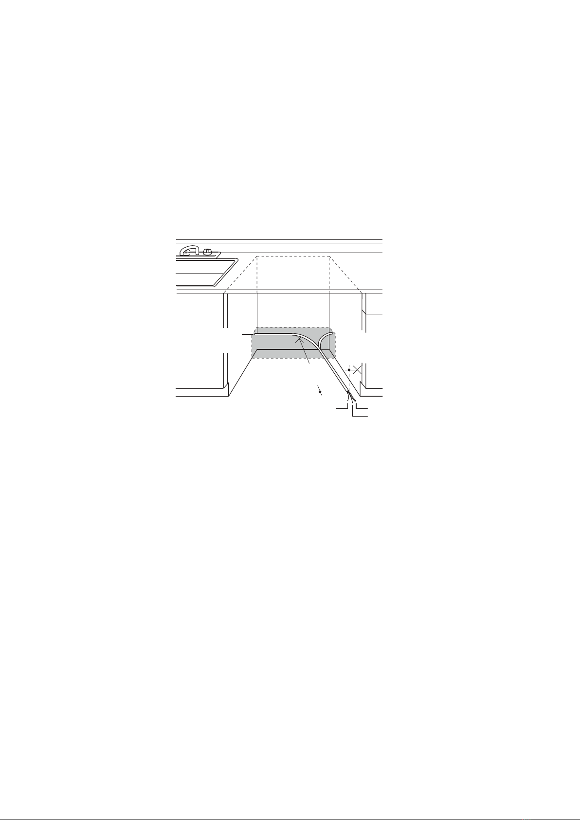
Cabinet preparation and wire routing
•The wiring may enter the opening from either side, the rear, or the floor within the shaded area.
•The electrical connection is on the front right of the dishwasher.
•Drill a 1.5 in. (3.81 cm) maximum diameter hole to run the electrical cable through the wall of the cabinet.
•The hole must be free of sharp edges. If the cabinet wall is metal, the hole edge must be covered with a bushing or
rubber grommet.
•Cable direct connections may pass through the same hole as the drain hose and hot water line, but power cords with
plugs must pass through a separate hole.
24 in. (60.96 cm)
from wall
1.5 in. (3.81 cm)
diameter hole (max.)
Ground Black
White
2.5–3.5 in. (6.5–9.0 cm)
from cabinet
7

UP DOWN
Preparing the hot water line
•The water connection is on the left side of dishwasher.
•The hot water line may enter the opening from either side, the rear, or the floor within the shaded area.
•The hot water line may pass through the same hole as the electrical and drain hose. Or, you can drill an additional 1.5 in.
(3.81 cm) maximum diameter hole for the hot water line.
•If a power cord with a plug is used, the hot water line may not pass through the same hole as the power cord.
Connecting the water line to the water supply
1Turn off the water supply.
2Install a hand shut-off valve in an accessible location, such as under the sink. This is optional, but strongly
recommended, and may be required by local codes.
3Install the hot water inlet line, using at least 3/8 in. O.D. copper tubing. Route the line as shown in the figure above and
extend it forward at least 18 in. (45.72 cm) from the rear wall of the enclosure.
4Adjust the water heater to a temperature of 120° F to 150° F (49° C to 65° C).
5Flush the water line to clean out any debris.
Note: The hot water pressure must be between 20 and 120 psi (138 and 827 kPa).
1.5 in. (3.81 cm) diameter hole (max.)
Shut-off valve
18 in. (45.72 cm) from wall
Hot
5.3–7.3 in.
(13.5–18.5 cm)
from cabinet
Cabinet face
3 in. (7.62 cm)
from floor
5.3–7.3 in.
(13.5–18.5 cm)
from cabinet
Water supply
line
Power cable
2.5–3.5 in.
(6.5–9.0 cm)
8

Installation instructions
Step 1: Install the decoration door to the outer door of the dishwasher
Install the hook and brackets on the decoration door.
1
Install the handle to the outer door.
2
C
C
B
B
Handle mounting holes
9

Put the hook into the slot of the outer door, for the positioning.
3
Fix the decoration door onto the outer door by screws and bolts.4
You’ll need:
Phillips screwdriver
D
1/4 in. and 5/16 in.
Nut driver
Screws D
ST3.5 x 45 (4)
Screws C
ST3.5 x 25 (2)
Screws B
ST4 x 14 (8)
Top Hook
Mounting Seats (2)
Brackets (2)
10
ATTENTON: you need an assistant to hold the top of the machine to prevent it forward.
Otros manuales para F24DWS650PR
2
Tabla de contenidos
Otros manuales de Lavavajillas de Forte

Forte
Forte F18DWS450PR Manual de usuario

Forte
Forte F24DWS650PR Manual de usuario

Forte
Forte F24DWS650PR Manual de usuario

Forte
Forte F18DWS450PR Manual de usuario

Forte
Forte 250 Series Manual de usuario

Forte
Forte F18DWS250SS Manual de usuario

Forte
Forte F24DWS450PR Manual de usuario

Forte
Forte F24DWS250SS Manual de usuario

Forte
Forte F24DWS450PR Manual de usuario

Forte
Forte F24DWS450PR Manual de usuario


