Echoflex Installation Guide
Elaho Light Sensor
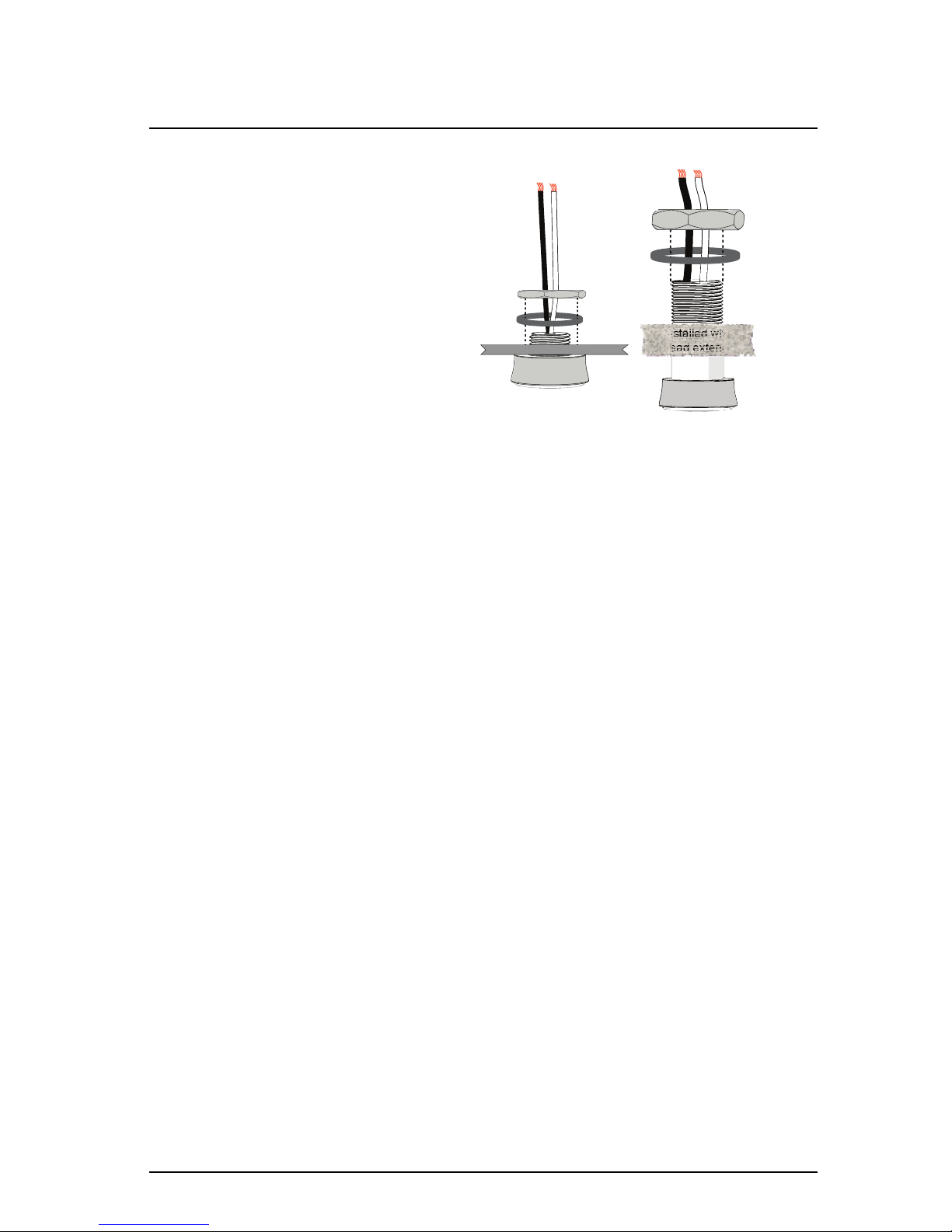
2. Terminate the incoming wire pairs from the remote Light Sensor
head(s) to the controller.
a. At the controller, strip 5/8” (9-10 mm) of insulation from the
ends of each installed head wire.
b. Using a small 1/8” (3,35 mm) flat blade or #1 Phillips
screwdriver, loosen the terminals on the “Primary Sensor” and
“Optional Sensor” connectors found on the Light Sensor
controller.
c. Insert the black (typical) wire from the first Light Sensor head
wire pair into terminal “1” of the “Primary Sensor” connector.
d. Insert the white (typical) wire from the first Light Sensor head
wire pair into terminal “2” of the “Primary Sensor” connector.
e. Repeat this process for the second wire pair, if installed, to the
“Optional Sensor” connector.
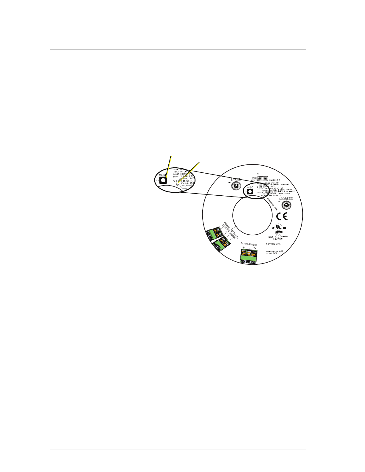
Sensor Configuration
The Elaho Light Sensor participates in an Elaho system using the configured
Space and Address, which are selectable using the rotary switches on the rear
panel of the sensor.
Additional DIP switches and the [Mode] button, also located on the rear panel,
set the sensor functionality and the sensor function with dark and bright
actions.
Set Space and Address
Two rotary switches on the rear panel
of the controller provide for
assignment of the sensor Space and
Address. By default, these switches are
set to Space 1, Address 1.
Do not duplicate a device Address
within the same Space.
Commands are shared by all devices
within a space.
DIP Switch Settings
DIP switches on the rear panel of the
Light Sensor controller provide for additional configuration options including
deadband sensitivity, delay time, and the ability to restore the sensor to its
factory defaults.
DIP Switch 1
DIP switch position 1 determines whether the sensor will use a Dimming
operation (Off) or a Switched operation (On). The default setting is Dimming
operation. Reference Sensor Operation on page11.
Elaho Light Sensor Page 8 of 12 Echoflex Solutions, Inc.