Cross Technologies 1582-10M Manual de usuario

Instruction Manual
Model 1582-10M
Protection Switch
January 2009 Rev O
MENU
EXECUTE
MODEL 1582
SWITCH CROSS TECHNOLOGIES INC.
REMOTECH1
1
POWER
2
CH2
ALARMS OUTPUT = CH1
AUTO
Data, drawings, and other material contained herein are proprietary to Cross Technologies, Inc.,
but may be reproduced or duplicated without the prior permission of Cross Technologies, Inc.
for purposes of operating the equipment.
When ordering parts from Cross Technologies, Inc., be sure to include the equipment
model number, equipment serial number, and a description of the part.
CROSS TECHNOLOGIES, INC.
6170 Shiloh Road
Alpharetta, Georgia 30005
(770) 886-8005
FAX (770) 886-7964
Toll Free 888-900-5588
WEB www.crosstechnologies.com
E-MAIL [email protected]

INSTRUCTION MANUAL
MODEL 1582-10M PROTECTION SWITCH
TABLE OF CONTENTS PAGE
Warranty 2
1.0 General 3
1.1 Equipment Description 3
1.2 Technical Specifications 4
1.3 Monitor and Control Interface 5
1.4 M&C Commands 6
2.0 Installation 8
2.1 Mechanical 8
2.2 Rear Panel Inputs and Outputs 8
2.3 Front Panel Controls and Indicators 8
2.4 Installation/Operation 9
2.5 Menu Settings 10
2.6 Use Information 13
WARRANTY - The following warranty applies to all Cross Technologies, Inc. products.
All Cross Technologies, Inc. products are warranted against defective materials and
workmanship for a period of one year after shipment to customer. Cross Technologies,
Inc.’s obligation under this warranty is limited to repairing or, at Cross Technologies, Inc.’s
option, replacing parts, subassemblies, or entire assemblies. Cross Technologies, Inc. shall
not be liable for any special, indirect, or consequential damages. This warranty does not
cover parts or equipment which have been subject to misuse, negligence, or accident by the
customer during use. All shipping costs for warranty repairs will be prepaid by the
customer. There are not other warranties, express or implied, except as stated herein.
CROSS TECHNOLOGIES, INC.
6170 Shiloh Road
Alpharetta, Georgia 30005
(770) 886-8005
FAX (770) 886-7964
Toll Free 888-900-5588
WEB www.crosstechnologies.com
E-MAIL [email protected]
1582-10 Manual Page 2 1/22/09

MODEL 1582-10M Protection Switch
1.0 General
1.1 Equipment Description - The 1582-10M 1:1 Switch, 10 MHz provides Auto, Manual or Remote relay
switching between CH1 and CH2, 10 MHz signals. Alarm conditions on CH1 and CH2 are a level drop below
-6 dBm of the 10 MHz signal. The 1582-10M switches from CH1 to CH2 only if CH1 alarms and CH2 is good.
The unit switches back when CH1 is no longer in alarm or both CH1 and CH2 are bad. When power is lost and
when power is applied (as alarms at power up dictate), CH1 is selected. Front panel LEDs indicate CH1 and
CH2 alarms, Remote mode (yellow), and redundant power supplies on (green). Multi-function push button
switches select Auto, Local, or Remote operation and the signal path in the Manual mode. Remote operation via
the RS232/RS485 M&C interface allows selection of CH1 or CH2 and indicates switch position and alarm
status. A contact closure to ground indicates if either or both CH1, CH2 are in alarm. An LCD display shows
Auto, Local or Remote operation and the signal path. Connectors are BNC, female for the 10 MHz signals and
DB9 for M&C and for the alarm contact closure output. The 1582-10M is a 1RU chassis with redundant power
supplies fed by separate fused 100-240 ±10% VAC AC input connectors.
MENU
EXECUTE
MODEL 1582
SWITCH CROSS TECHNOLOGIES INC.
REMOTECH1
1
POWER
2
CH2
ALARMS OUTPUT = CH1
AUTO
AC1
GND
J1
J13
CH1
INPUT
J19
AND
MONITOR
CONTROL
15 234 6789
AC2
J5
CH2
INPUT REFERENCE OUTPUTS
J20 J6 J7 J8 J9 J10 J11 J12
(4 or 8 Ports Optional)
(Ethernet Optional)
1582-10M FRONT AND REAR PANEL
SWITCHED
10 MHZ OUT
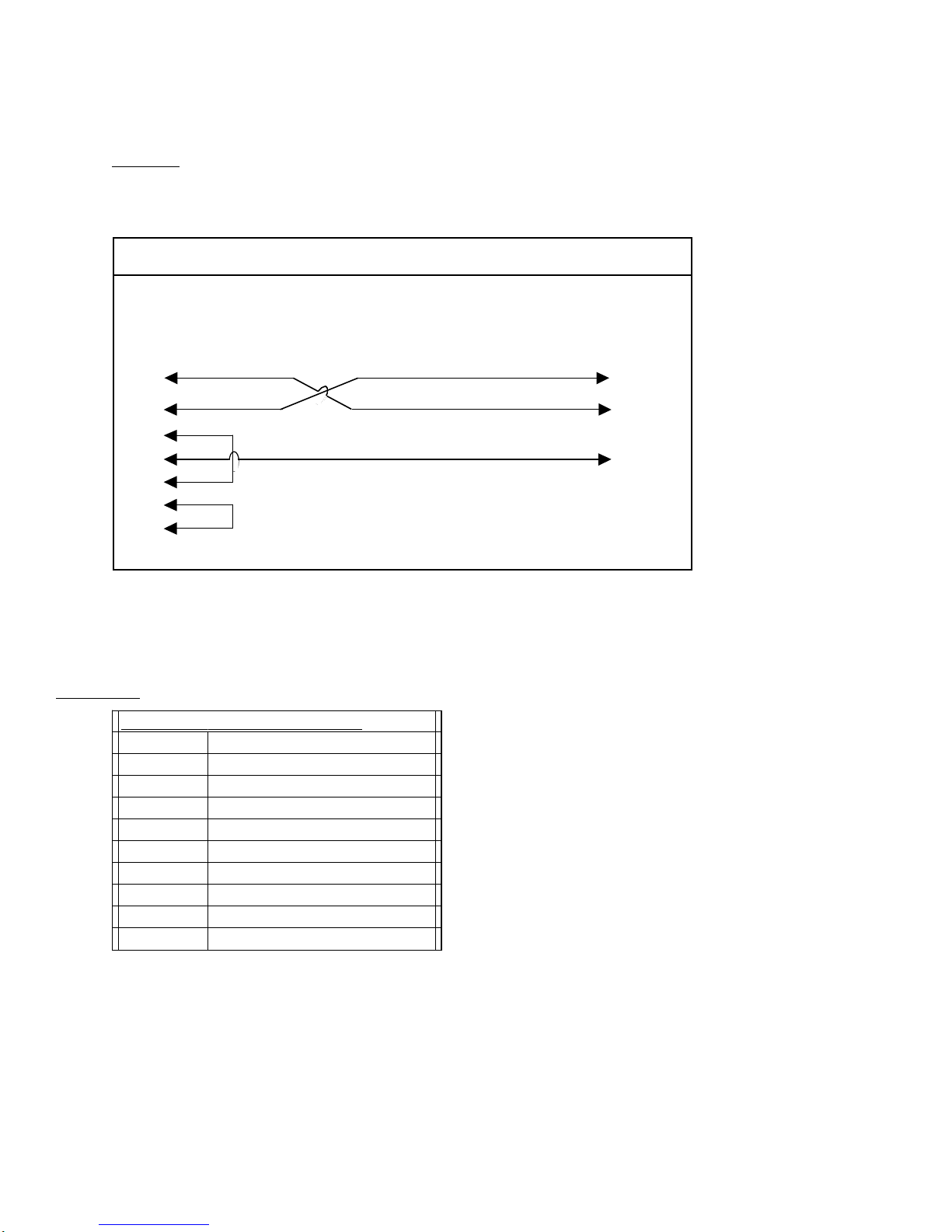
1582-10M BLOCK DIAGRAM
CH 1 IN
10 MHz
CH 2 IN
10 MHz
CONTROLLER
ALARM
DET CH1
ALARM
DET CH2
MULTI-
FUNCTION
SWITCHES
M&C SUMMARY ALARM
CONTACT CLOSURE
OUTPUT = CH1
AUTO
1582-10 Manual Page 3 1/22/09

1.2 Technical Specifications
1582-10M Technical Specifications
Switch Characteristics
Impedance 75 ohms
Type Non-latching Relay
Isolation >50 dB DC to 10 MHz
Switch level/time -6±1dB / 100 milliseconds
Insertion Loss 1 dB
Configuration SPDT
Alarm and Control, M&C
Alarm output signal Form C relay: 30VDC, 0.5A max
M & C Interface RS232C or RS485, selectable, (Ethernet Optional)
M & C Signal 38.4 kB baud rate
Controls, Indicators
Mode Select Local/Remote, Auto/Manual - push-button switches,
contact closures, or remote selection
Power On Status Green LEDs, (PS1, PS2),
Remote Select Status Yellow LED, M&C serial
Manual Select Status M&C serial
Alarm Status Red LEDs , External Form C contact closure, M&C serial
Connectors, Other
Ext. Alarm, M&C Conn. DB9 (female)
10 MHz In/Out BNC, female, 75 ohm
Size 1 RU, 19 inch standard chassis 1.75” high X 16.0” deep
Power Redundant 100 - 240 ±10% VAC, 47 - 63 Hz, 20 W max. power supplies
Options
- 4 4 - 75outputs
- 8 8 - 75outputs
- W8 Ethernet M&C
*Specifications subject to change without notice
1582-10 Manual Page 4 1/22/09
1.3 Monitor and Control Interface
A) Remote serial interface
Protocol: RS-232C, 9600 baud rate, no parity, 8 data bits, 1 start bit, and 1 stop bit.
(RS-232C, RS-422, or RS-485 - option -Q)
1
2
3
4
5
6
7
8
9
1
2
3
4
5
6
7
8
9
Female DB-9
PC Com Port Male DB-9
2015/16/17 M&C Port
M&C Cable Diagram - Cross Technologies Frequency Converters
Connector: Rear panel, DB-9 female
J10 Pinouts (RS-232C/422/485)
J10 Pinouts (RS-232C/422/485)
Pin Function
1Rx-
2 Rx+ (RS-232C)
3 Tx+ (RS-232C)
4Tx-
5GND
6 Alarm Relay: Common
7 Alarm Relay: Normally Open
8NotUsed
9 Alarm Relay: Normally Closed
1582-10 Manual Page 5 1/22/09

1.4 M&C Commands
The following tables summarize the commands and status queries applicable to the
1582-10M Protection Switch.
*PLEASE NOTE: The two character {aa} prefix, shown in the table below, is present ONLY when RS485 is selected.
Table 2.0 Model 1582-10M - M&C Remote Commands
x = 1: enables min. auto switchin
g
mode
where:{aaCMx}In Auto Switching Mode
x = 2: remote select CH2
x = 1: remote select CH1
x = 0: disables min. auto switchin
g
mode
x = 0: clears remote selections
where:
{
aaCRx
}
Remote Select
DescriptionSyntaxCommands
Table 2.0: Model 1582-10M M&C Remote Commands
1.5 M&C Queries
Table 2.1 Model 1582-10M - M&C Status Commands
X = 1 if min. auto switching is enabled
X = 0 if min. auto switching is disabled
returns: {aaSMx} where:
{
aaSM
}
In Auto Switching Mode Status
X = 2 if CH2 is remotely selected
X = 1 if CH1 is remotely selected
X = 0 if no remote selections
returns: {aaSAx} where:
{
aaSR
}
Remote Select Status
returns: {aaSV 1582-10M v 400} model # & firmware version
{
aaSV
}
Model # and firmware version
DescriptionSyntaxCommands
Table 2.1: Model 1582-10M M&C Status Commands
Continued on page 7 ...
1582-10 Manual Page 6 1/22/09

Table 2.2 Model 1582-10M - M&C Status Commands - Continued
y = 2 if switch mode is Manual
y = 1 if switch mode is Remote
y = 0 if switch mode is Auto
X = 2 if CH2 is selected
X = 1 if CH1 is selected
returns: {aaSPxy} where:{aaSP}
y = 1 if CH2 is alarmed
y = 0 if CH2 is not alarmed
Switch Position
X = 1 if CH1 is alarmed
X = 0 if CH1 is not alarmed
returns: {aaSAxy} where:{aaSA}
Alarms Status
DescriptionSyntaxStatus Commands
Table 2.1: Model 1582-10M M&C Status Commands - Continued
1582-10 Manual Page 7 1/22/09

2.0 Installation
2.1 Mechanical - The 1582-10M is rack mounted by attaching the front panel to a rack through the four holes
at the edges of the panel.
2.2 Front and Rear Panel Controls and Indicators - The following are the front and rear panel controls and
indicators.
AC1
GND
J1
J13
CH1
INPUT
J19
AND
MONITOR
CONTROL
15
234 6789
AC2
J5
CH2
INPUT REFERENCE OUTPUTS
J20 J6 J7 J8 J9 J10 J11 J12
(4 or 8 Ports Optional)
(Ethernet Optional)
MENU
EXECUTE
MODEL 1582
SWITCH CROSS TECHNOLOGIES INC.
REMOTECH1
1
POWER
2
CH2
ALARMS OUTPUT = CH1
AUTO
AC1, AC2 - POWER IN
AC inputs for switching power
supplies. 100-240 ± 10%
VAC, 47-63 Hz.
CH1 LED illuminates red when
the 10 MHz input to CH1
drops below -6 dBm
CH2 LED illuminates red
when the 10 MHz input to CH2
drops below -6 dBm
REMOTE LED illuminates
yellow when the remote
interface is enabled.
POWER 1, 2 illuminates green
when the respective power
supplies are on.
FIGURE 2.3 1582-10M Front AND REAR Panel Controls and Indicators
1582-10 Manual Page 8 1/22/09

2.3 Installation / Operation
2.3.1 Installing and Operating the 1582-10M, Protection Switch Section
1. Connect primary 10 MHz signal to CH1 In/out, J13
2. Connect backup 10 MHz signal to CH2 In/out, J1
3. Connect selected 10 MHz output, J5, to external equipment.
4. Connect primary 100-240 ±10% VAC, 47 - 63 Hz to AC1 on the back panel.
5. Connect secondary 100-240 ±10% VAC, 47 - 63 Hz to AC2 on the back panel.
6. Set the gain for -10 to +30 dB. Make sure the output stays within -20 to 0 dBm with the gain selected
7. AC Fuse - The fuse is a 5 mm X 20 mm, 2 amp slow blow (Type T) and is inserted in the far slot in the
drawer below the AC input as shown in Figure 2.3. There is a spare fuse in the near slot.
NOTE: If a fuse continues to open, the power supply is most likely defective.
FUSE DRAWER
SPARE FUSE DRAWER
AC Fuse - 2 amp slow blow (Type T 2A GDC),
5 mm X 20 mm
~
INPUT
100-240± 10%VAC
47-63 Hz
2A MAX
FUSE
TYPE T 2A GDC
250 VOLT
FOR 100 - 240 V~
~
FIGURE 2.4 Fuse Location and Spare Fuse
1582-10 Manual Page 9 1/22/09

2.4 Menu Settings
2.4.1 Functions
This section describes operation of the front panel controls. There are three operator switches, the LCD display
and alarm indicator LEDs. All functions for the equipment are controlled by these components. The functions
are (see Figure 2.3):
Power Up
Normal Display
Menu 1 Manual Select
Menu 2 Remote Enable
Menu 3 Interface
Menu 4 RS-485 Address
Menu 5 Minimum Auto Switching
Save Menu When “R” is selected in any above menu, or when the end is reached (after Menu 11)
All program changes must start with the operation of the Menu/Execute switch and must also end with the
operation of the Menu/Execute switch verified by the “Save Settings?” Menu. If this sequence is not followed,
none of the changes will take effect. If programming is initiated and no operator action takes place for
approximately 12 seconds (before the final press of the Menu/Execute switch) the display will revert to its
previous status and you will need to start over.
1582-10 Manual Page 10 1/22/09
Tabla de contenidos
Otros manuales de Cambiar de Cross Technologies

Cross Technologies
Cross Technologies 1582-725 Manual de usuario

Cross Technologies
Cross Technologies 1582-70L Manual de usuario

Cross Technologies
Cross Technologies 1582-25L Manual de usuario

Cross Technologies
Cross Technologies 1582-03 Manual de usuario

Cross Technologies
Cross Technologies 1582-71 Manual de usuario

Cross Technologies
Cross Technologies 1582-225L2 Manual de usuario

Cross Technologies
Cross Technologies 1582-650 Manual de usuario

Cross Technologies
Cross Technologies 1582-22L Manual de usuario

Cross Technologies
Cross Technologies 1582-421L Manual de usuario

Cross Technologies
Cross Technologies 1582-14 Manual de usuario


