The Model 2082-14x-series of Redundant Unit Controllers are designed
to power, monitor and control LNA or LNB amplifiers configured in 1:1
or 1:2 redundancy modes. There are currently two (2) Drive Voltages
supported (+26 or +47 VDC) and two (2) Common (voltage or ground)
configurations. This manual addresses all eight (8) of these models as
shown in this chart:
Front panel LEDs indicate power, status (online, standby, alarm), and
MODEL 2082-14x-series - 1:1 & 1:2 Redundant Unit Controllers
1.0 General
1.1 Equipment Description
mode (auto, manual, local, remote). Up to 600 ma is available to power each amplifier. LNA or LNB current is measured and a fault
is signaled if the current deviates from user selected thresholds. Multi-function switches select Auto, Local, or Remote operation,
(Priority for 1:2 models), and the signal path in the Manual mode. Remote operation via the RS232/RS485 M&C interface allows
selection of priorities (1:2) and the signal path. Ethernet is available as option, -W8, -W18, or -W28. Contact closure to ground inputs
allow selection of Local/Remote, andAuto/Manual Modes. An LCD display shows each amplifier's current, and signal path. Form C
relay contact closures indicate amplifier and power supply status, waveguide switch position, Auto, Remote, and Manual operation.
Connectors are DB37 for contact closure I/Os, MS3112E16-23S for the amplifier plate signals, and DB9s for monitor and control and
auxiliary external contact closure alarm inputs. ALL 2082-14x models are housed in a 1RU chassis which are powered by redundant
power supplies fed by separate, fused 100-240 ±10% VAC AC input connectors.
MENU
EXECUTE
MODEL 2082
CROSS TECHNOLOGIES INC.
CONTROLLER
UNIT 1 UNIT 2 UNIT 3
1
POWER
STATUS
STATUS
MODE
2312
ALARM
STDBY
ONLINE
MANUAL
LOCAL
REMOTE
AUTO
PATH
Figure 1.0 TYPICAL FRONT PANEL (1:2 model 2082-142 shown above)
AC1
GND I/O FUSE
UNIT 1
PLATE ASSY
AC2
GND
J4
FUSE
UNIT 2 FUSE
UNIT 3
15 234 20212223
610 789 25262728
1115 121314 30313233
19 161718 242934353637
F3F2F1J1
MONITOR
AND
CONTROL
J3A
EXT
ALARM
J3B VDC VDC VDC
DS3DS2DS1J2
15
234 6789
15
234 6789
Figure 1.1 TYPICAL REAR PANEL - Shown with optional Ethernet Connector (J2) (1:2 model 2082-142 shown above)
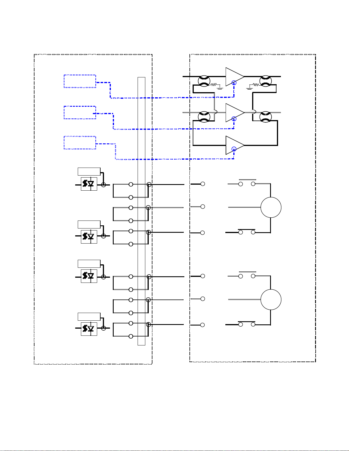
CH 1 CH 1
PLATE ASSY
2082-141-series
PLATE ASSY
2082-142-series
Figure 1.2: (TYPICAL) Block Diagrams, 1:1 (2082-141-series) and 1:2 (2082-142-series) Configurations
2082-14x-series Manual, Rev. F Page 3 05/30/18