6 720 610 599 GB (03.02)
2
Contents
Contents
Safet precautions 3
S mbols 3
1 Details of the appliance 4
1.1 EC Declaration of Conformity 4
1.2 Standard package 4
1.3 Description of appliance 4
1.4 Accessories 5
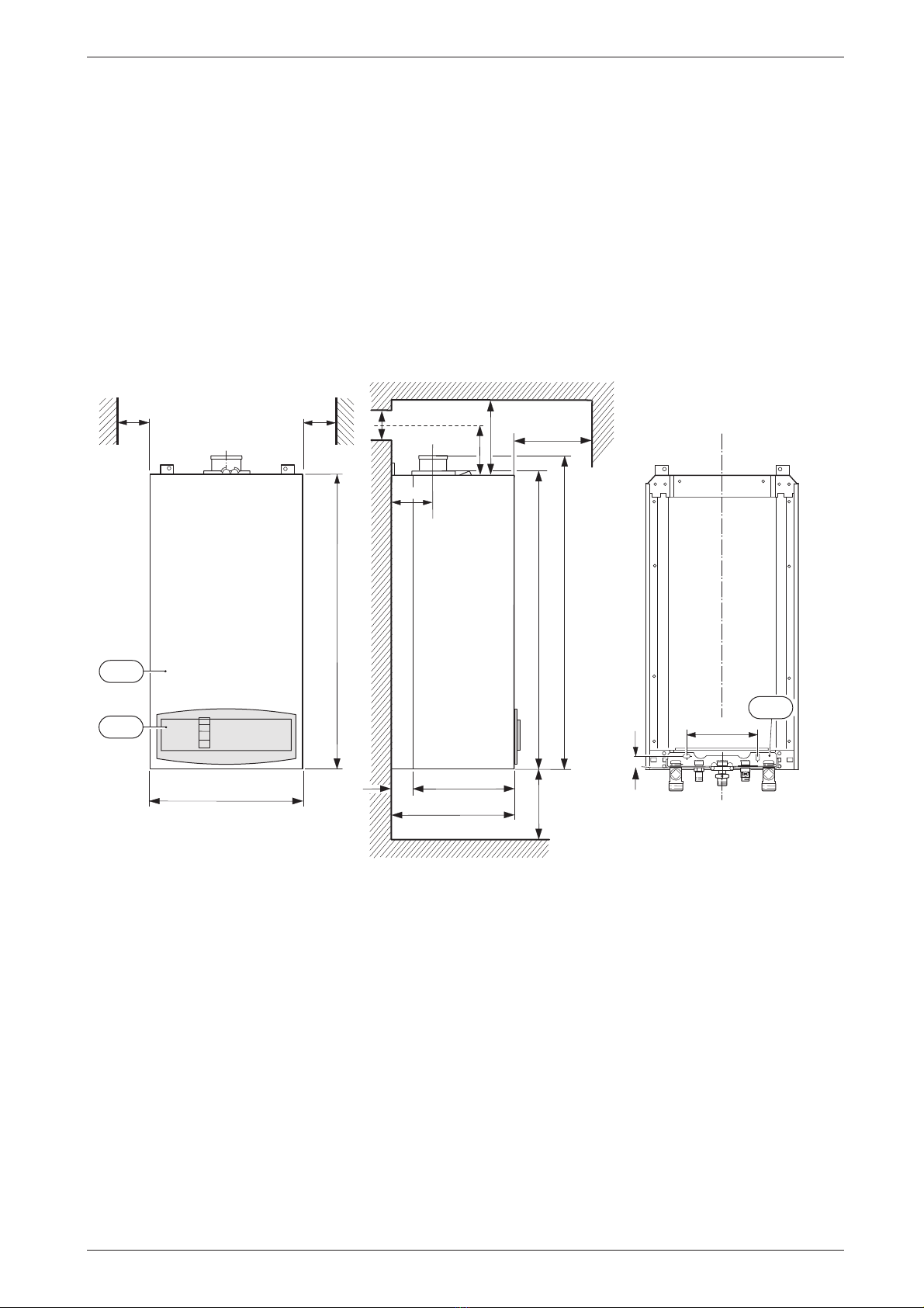
1.5 Casing dimensions 5
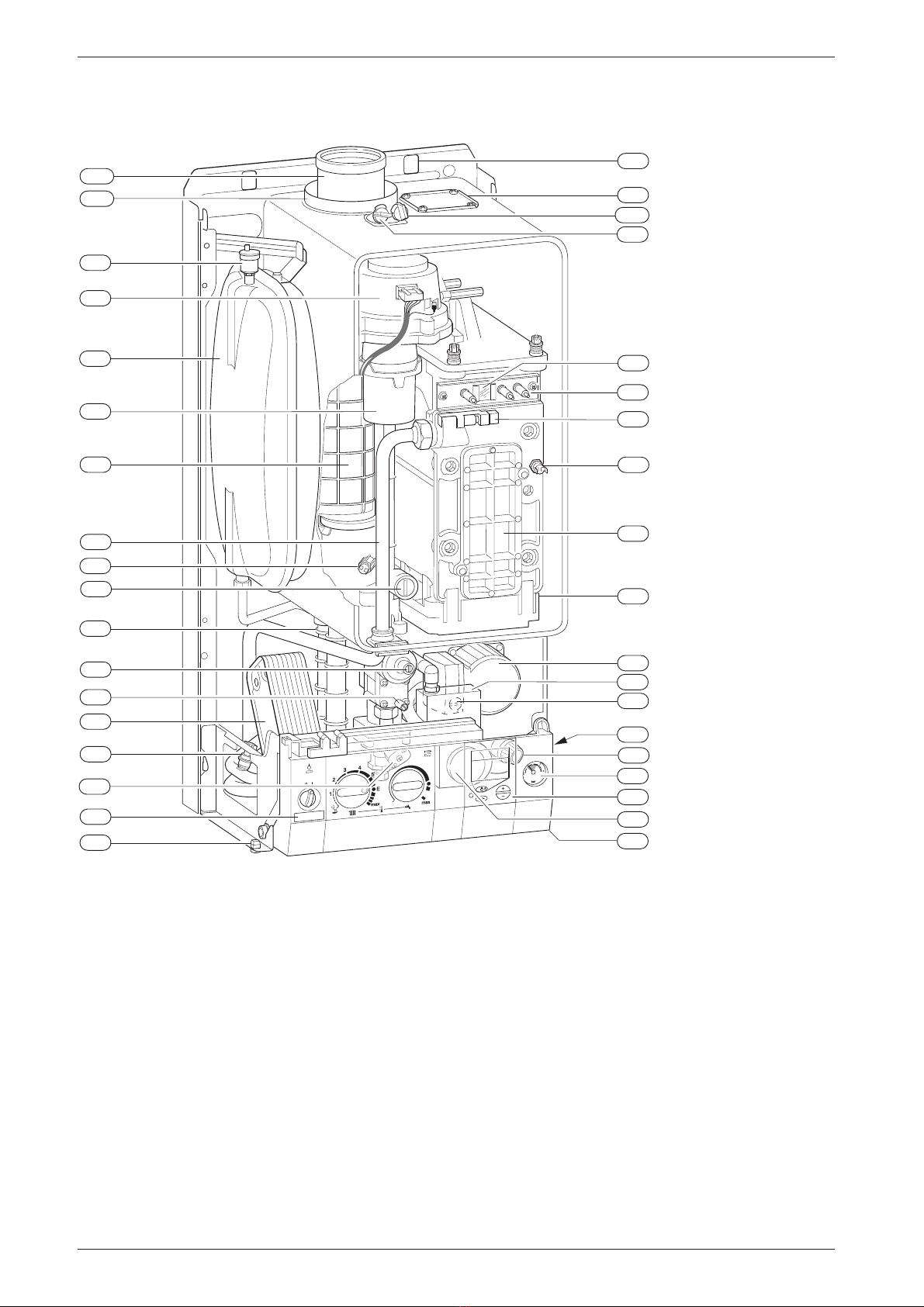
1.6 Layo t of appliance 6
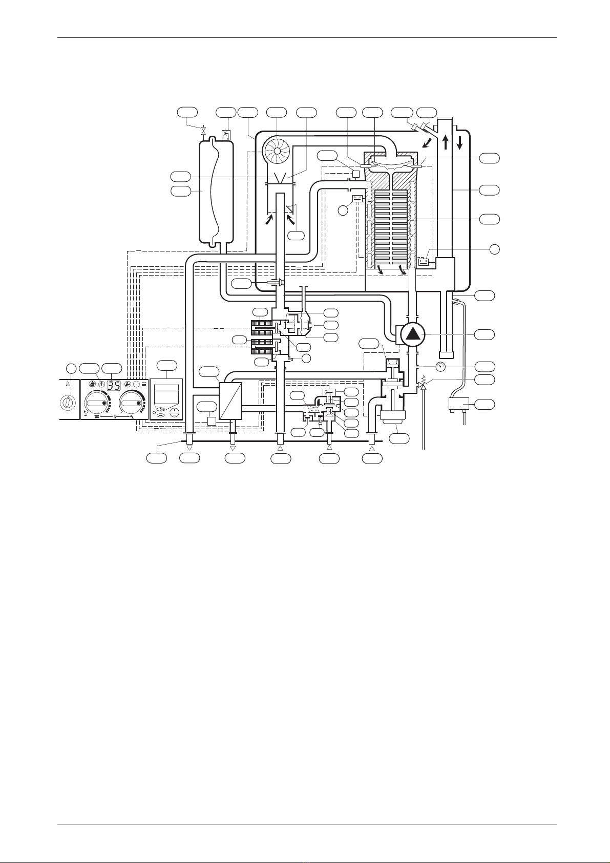
1.7 F nction 7
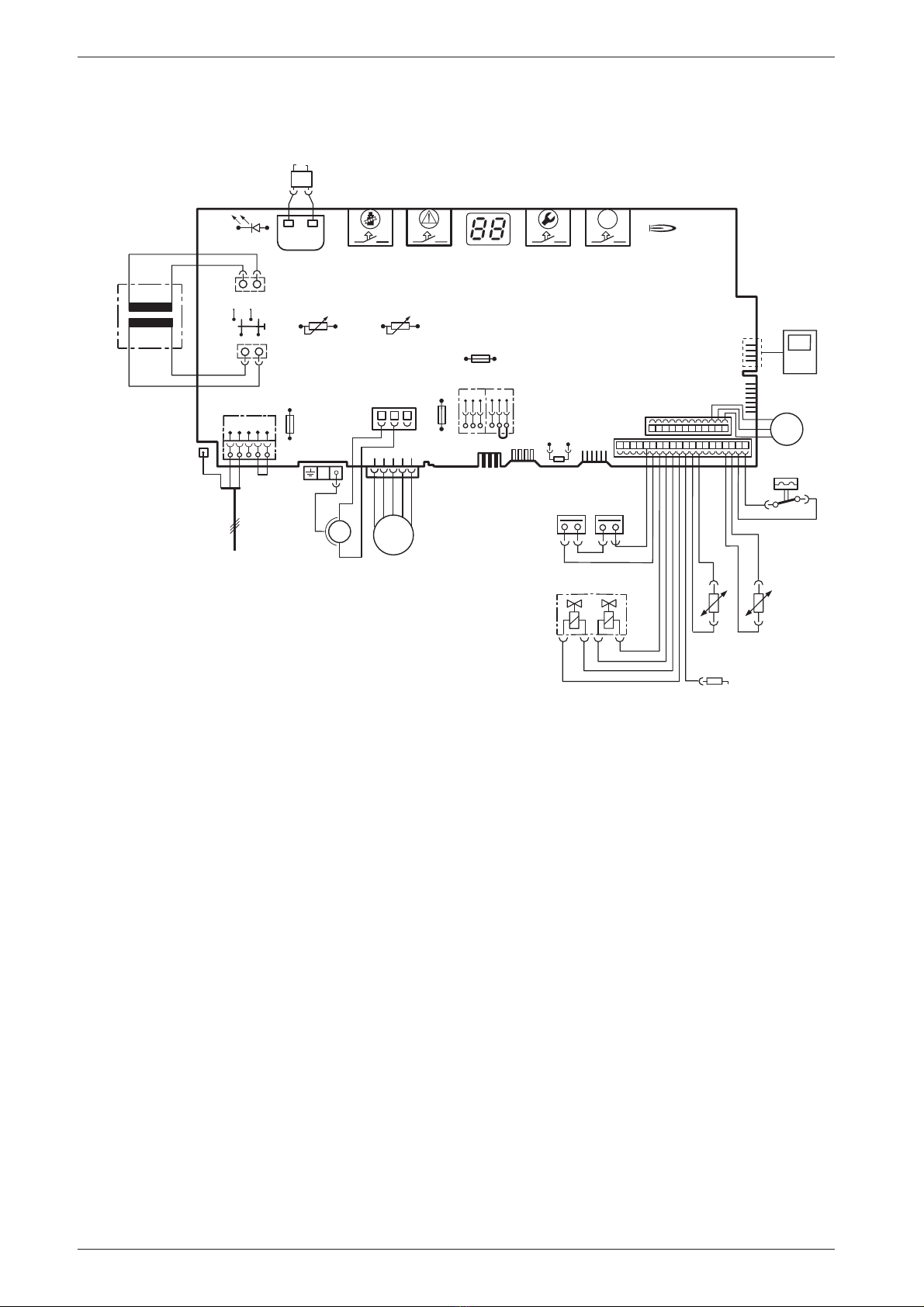
1.8 Electrical wiring diagram 8
1.9 Technical data 9
2 Installation regulations 10
3 Installation 11
3.1 Important remarks 11
3.2 Domestic hot water 11
3.3 Sealed systems 11
3.4 Siting the appliance 12
3.5 Wall mo nting frame assembly 13
3.6 Pre-piping the system 13
3.7 Fitting the appliance 14
3.8 Checking the connections 15
3.9 Fl e Systems 15
3.9.1 Siting the Fl e Terminal 16
3.9.2 Installation of the fl e 17
3.9.3 Fl e d ct preparation and assembly 19
4 Electrical connections 20
4.1 Connecting the appliance 20
4.2 Mains Voltage external controls connections 21
5 Commissioning 22
5.1 Commissioning 22
5.2 Switching the appliance on/off 23
5.3 Switching on the central heating 23
5.4 System controls 23
5.5 Setting the domestic hot water temperat re
and flow rate 24
5.5.1 Domestic hot water temperat re 24
5.5.2 Hot water flow rate 24
5.6 S mmer mode (hot water only) 24
5.7 Frost protection 24
5.8 P mp anti-seize f nction 24
5.9 Fa lt Condition 25
5.10 Digital Timer 26
5.10.1Basic Settings 26
5.10.2B tton F nctions 26
5.10.3Programming 26
5.10.4Setting time and day 26
5.10.5Setting the timed periods 26
5.10.6Changing the Operating Mode 27
5.10.7Deleting Settings 27
5.10.8Completing Programming 27
5.10.9Time Display 27
6 Individual settings 28
6.1 Mechanical settings 28
6.1.1 Checking the size of the expansion vessel 28
6.1.2 Setting the central heating flow temperat re 28
6.1.3 Changing the heating p mp characteristic 28
6.2 Settings on the Bosch Heatronic 29
6.2.1 Operating the Bosch Heatronic 29
6.2.2 Selecting the p mp control mode for central
heating mode (Service F nction 2.2) 29
6.2.3 Setting the anti-cycle time
(Service F nction 2.4) 29
6.2.4 Setting the maxim CH flow temperat re
(Service F nction 2.5) 30
6.2.5 Setting the switching difference
(Service F nction 2.6) 30
6.2.6 Setting the heating o tp t
(Service F nction 5.0) 30
6.2.7 Constant hot water cycle time
(Service F nction 6.8) 30
6.3 Setting the gas/air ratio 30
7 Converting the appliance to
different gas t pes 31
7.1 Setting the gas/air ratio 31
7.2 Testing comb stion air/fl e gas at
set heat o tp t 33
7.2.1 Testing the O
2
or CO
2
level in
the comb stion air 33
7.2.2 Testing CO and CO
2
33
8 Maintenance 33
8.1 Pre-Service Check List 34
8.2 Description of servicing operations 35
8.3 Replacement of Parts 38
8.3.1 PCB control board and transformer 38
8.3.2 Fan Assembly 39
8.3.3 P mp 39
8.3.4 3-way diverter valve 40
8.3.5 3-way diverter valve motor 40
8.3.6 Sensors 40
8.3.7 Gas Valve 41
8.3.8 Domestic Hot Water Heat Exchanger 41
8.3.9 Electrode assembly 41
8.3.10Press re ga ge 41
8.3.11Expansion vessel 41
8.3.12Press re Relief Valve 41
8.3.13B rner 41
8.3.14Flow switch 42
8.3.15Primary Heat Exchanger 42
9 Appendix 43
9.1 Fa lt Codes 43
9.2 Short parts list 44
9.3 Heating/hot water o tp t settings (N.G) 45
9.4 Heating/hot water o tp t settings (L.P.G) 45
9.5 Operational Flow diagrams 46
9.5.1 Domestic hot water f nction 46
9.5.2 Central heating f nction 47