AURES TRP100 Manual de usuario
All specifications are subject to change without notice
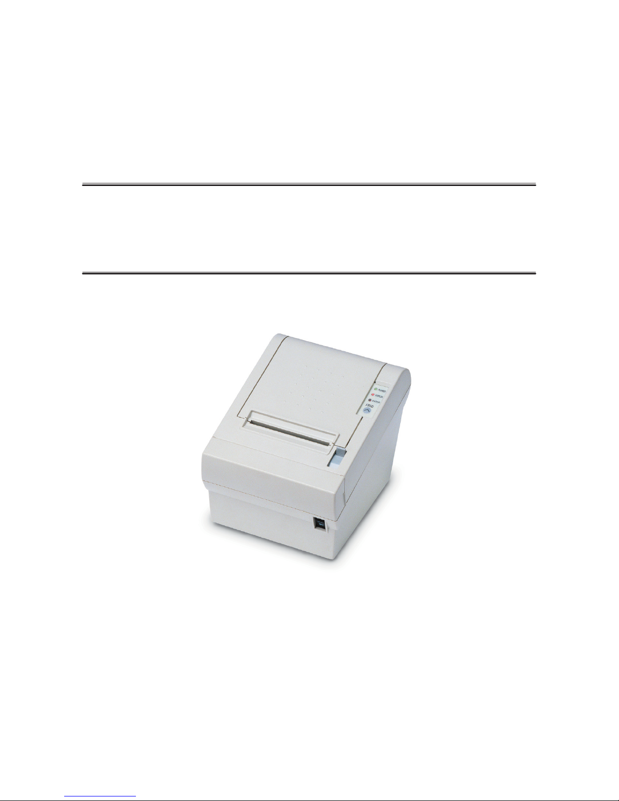
TRP-100
Receipt Printer User’s Manual


TRP-100 User’s Manual
3
1. Parts Identifications
TABLE OF CONTENTS
1. Parts Identifications 3
2. Setting up the printer 4
2.1 Unpacking 4
2.2 Connecting the cables 5
2.3 Loading the roll paper 9
2.4 Dip switch setting 11
3. Control panel and other functions 17
3.1 Control panel 17
3.2 Error Indicating 17
4. Self Test 18
5. Hexadecimal Dump 19
6. Specifications 20
6.1. General Specifications 20
6.2. Auto Cutter Specifications 22
6.3. Interface 22
6.4. Electrical Characteristics 22
6.5. Environmental Requirements 23
6.6. Reliability 23
6.7. Certification 23
6.8. Black Mark specifications 24
7. Command List 25

TRP-100 User’s Manual
4
TRP-100 User’s Manual
5
2-2. Connecting the Cables
You can connect up the cables required for printing to the printer.
They all connect to the connector panel on the back of the printer, which is shown below :
Before connecting any of the cables, make sure that both the printer and the computer are turned
off.
2. Setting Up the Printer
2-1. Unpacking
Your printer box should include these items. If any items are damaged or missing, please contact
your dealer for assistance.
The Printer User's Manual Roll Paper
Adaptor(Option) Interface Cable(optional)

TRP-100 User’s Manual
6
TRP-100 User’s Manual
7
Centronics Parallel Interface
PIN SIGNAL I/O DESCRIPTION
1 STROBE- Input Synchronize signal Data received
2~9 DATA0~7 Input/Output Data bit Transmitted 0~7
10 ACK- Output Data receiving completed.
11 BUSY Output Impossible to print of data receiving.
12 PE Output Paper empty
13 SELECT Output Printer status for ON/OFF line
14 AUTO FEED- Input Paper auto feed signal
15 GROUND - System ground
16 GROUND - System ground
17 NC -
18 LOGIC-H - +5V
19~30 GROUND - System ground
31 INIT- Input Initialize
32 ERROR- Output Printer error
33 GROUND - System ground
34 NC -
35 +5V - +5V
36 SELLECT IN- Input Printer select signal
Ethernet Interface
PIN SIGNAL I/O
1 Data Out + Output Data +
2 Data Out - Output Data -
3 GND Ground
4 Data IN + Input Data +
5 Data IN - Input Data -
6 N.C
7 N.C
8 N.C
2-2-1. Interface Connector
<D-SUB 25 Female Serial> <Centronics Parallel>
<USB “B” Type> <Ethernet>
<USB COMBO> <Wi-fi>
Serial Interface
PIN SIGNAL I/O DESCRIPTION
2 TXD Output Printer transmit data line RS-232C level
3 RXD Input Printer receive data line RS-232C level
4, 20 DTR Output Printer handshake to host line RS-232C level
6 DSR Input Data Send Ready
1, 7 GND - System Ground
USB Interface
PIN SIGNAL I/O DESCRIPTION
1 +5V - +5V
2 DATA- - Printer transmit data line
3 DATA+ - Printer transmit data line
4 GND - System Ground
TRP-100 User’s Manual
8
TRP-100 User’s Manual
9
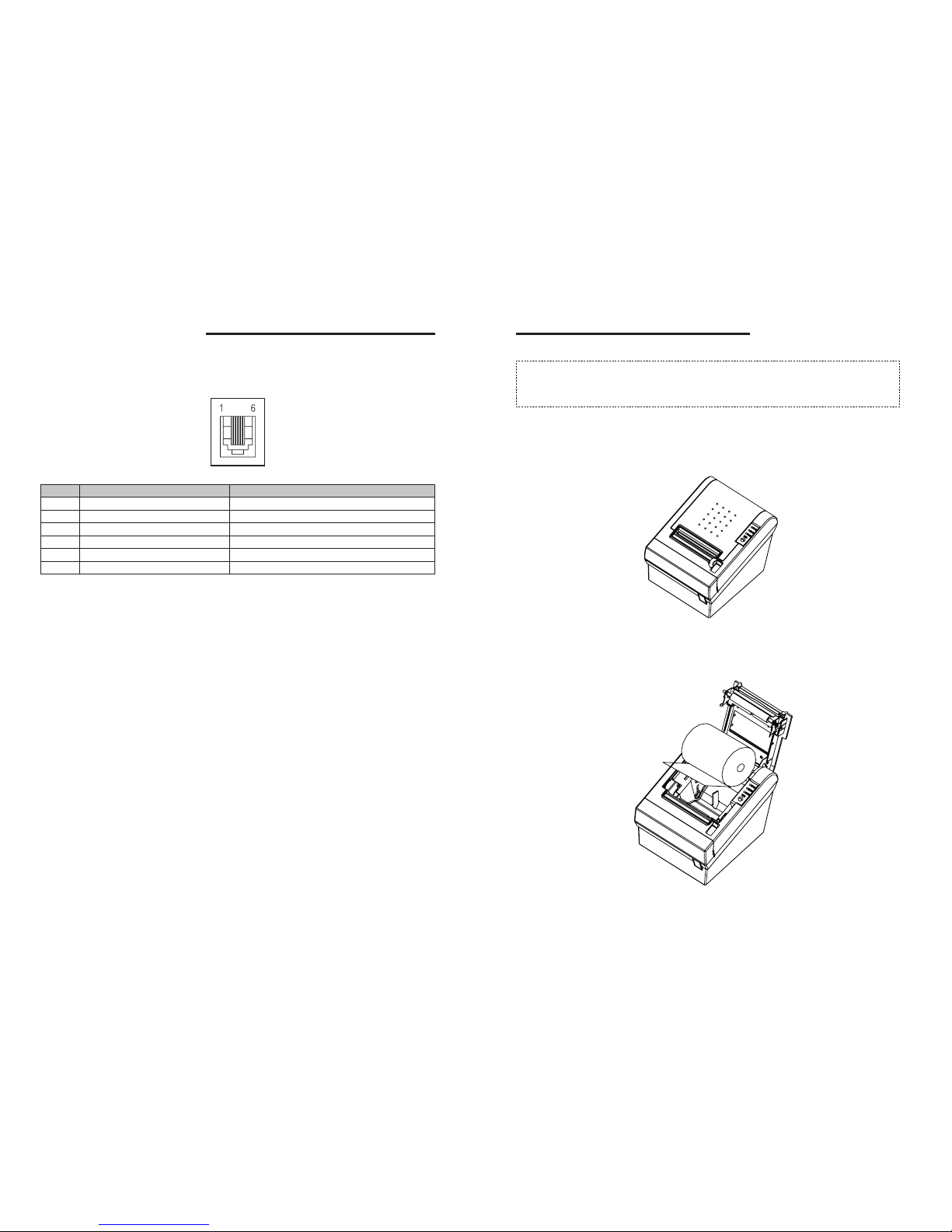
2-3. Loading the Roll Paper
Notes: Be sure to use paper rolls that meet the specifications. Do not use paper rolls
that have the paper glued to the core because the printer cannot detect the paper end
correctly. (Turn off power switch)
1. Make sure that the printer is not receiving data; Otherwise, data may be lost.
2. Open the paper roll cover by pushing down the cover open button.
3. Remove the used paper roll core if there is one inside.
4. Insert new paper roll as shown.
2-2-2. Cash Drawer Connector
The printer can operate two cash drawers with a 6 pin RJ-11 modular connector.
The driver is capable of supplying a maximum current of 1.0A/24VDC for 510ms or less
when not printing.
PIN SIGNAL DESCRIPTION
1 Signal GND -
2 Drawer kick-out drive signal 1 Output
3 Drawer open/close signal Input
4 +24V -
5 Drawer kick-out drive signal 2 Output
6 Signal GND -
Caution : To avoid an overcurrent, the resistance of the drawer kick-out solenoid must be 24 Ω
or more.

TRP-100 User’s Manual
10
TRP-100 User’s Manual
11
2-4. Dip Switch Setting
The printer is set up at the factory to be appropriate for almost all users. On the other hand,
offers some more settings for users with special requirements.
It has DIP switches that allow you to change communication setting, such as handshaking and
parity check, as well as print density.
Your printer has two sets of DIP switches. The functions of the switches are shown in the following
tables.
♣Note : Power off. And open the cover of Dip Switch and change setting.
2-4-1. Serial Interface Specification
DIP Switch Set 1 Functions
SW FUNCTION ON OFF DEFAULT
1 Data Receive Ignored Print “?” OFF
2 Hexadecimal HEXDUMP NORMAL OFF
3 Hand Shaking XON/XOFF DTR/DSR OFF
4 Data Length 7bits 8bits OFF
5 Parity Check ENABLED DISABLED OFF
6 Parity Check EVEN ODD OFF
Baudrate selection
Transmission speed SW-7 SW-8
4800 bps ON ON
9600 bps OFF ON
19200 bps ON OFF
38400 bps OFF OFF
Print Density
Print Density SW-9 SW-10
Low Power ON ON
Normal OFF ON
Normal ON OFF
Dark OFF OFF
5. Be sure to note the correct direction that the paper comes off the roll.
6. Pull out a small amount of paper, as shown. Then, close the cover.
7. Tear off the paper as shown.

TRP-100 User’s Manual
12
TRP-100 User’s Manual
13
2-4-4. USB Interface Specification
DIP Switch Set 1 Function
SW FUNCTION ON OFF DEFAULT
2 Hexadecimal HEXDUMP NORMAL OFF
Print Density
Print Density SW-9 SW-10
Low Power ON ON
Normal OFF ON
Normal ON OFF
Dark OFF OFF
-------------------------------------------------old USB--------------------------------------------------------
DIP Switch Set 1 Functions
SW FUNCTION ON OFF DEFAULT
1 Data Receive Ignored Print “?” OFF
2 Hexadecimal HEXDUMP NORMAL OFF
3 Hand Shaking XON/XOFF DTR/DSR OFF
4 Data Length 7bits 8bits OFF
5 Parity Check ENABLED DISABLED OFF
6 Parity Check EVEN ODD OFF
Baudrate selection
Transmission speed SW-7 SW-8
4800 bps ON ON
9600 bps OFF ON
19200 bps ON OFF
38400 bps OFF OFF
Print Density
Print Density SW-9 SW-10
Low Power ON ON
Normal OFF ON
Normal ON OFF
Dark OFF OFF
--------------------------------------------------------------------------------------------------
2-4-2. Parallel Interface Specification
DIP Switch Set 1 Function
SW FUNCTION ON OFF DEFAULT
2 Hexadecimal HEXDUMP NORMAL OFF
5 Bi-Parallel mode DISABLED ENABLED OFF
Print Density
Print Density SW-9 SW-10
Low Power ON ON
Normal OFF ON
Normal ON OFF
Dark OFF OFF
2-4-3. USB COMBO Interface Specification
DIP Switch Set 1 Function
SW FUNCTION ON OFF DEFAULT
2 Hexadecimal HEXDUMP NORMAL OFF
COMBO Serial Option
SW FUNCTION ON OFF
3 HANDSHAKING XON/XOFF DTR/DSR
4 DATA LENGHT 7BITS 8BITS
5 PARITYCHECK ENABLED DISABLED
6 PARITYCHECK EVEN 0DD
Baudrate selection
Transmission speed SW-7 SW-8
4800 bps ON ON
9600 bps OFF ON
19200 bps ON OFF
38400 bps OFF OFF
Print Density
Print Density SW-9 SW-10
Low Power ON ON
Normal OFF ON
Normal ON OFF
Dark OFF OFF

TRP-100 User’s Manual
14
TRP-100 User’s Manual
15
♣CAUTION:
Turn off the printer while removing the DIP switch cover to prevent an electric short, which can
damage the printer.
1. Make sure the printer is turned off.
2. Remove the screw from the DIP switch cover. Then, take off the DIP switch cover as shown in
the illustration below.
3. Set the switches using a pointed tool, such as tweezers or a small screwdriver.
4. Replace the DIP switch cover. Then, secure it with the screw.
The new settings take effect when you turn on the printer.
2-4-5. Wi-fi Specification
DIP Switch Set 1 Function
SW FUNCTION ON OFF DEFAULT
2 Hexadecimal HEXDUMP NORMAL OFF
Print Density
Print Density SW-9 SW-10
Low Power ON ON
Normal OFF ON
Normal ON OFF
Dark OFF OFF
2-4-6. Ethernet Interface Specification
DIP Switch Set 1 Function
SW FUNCTION ON OFF DEFAULT
2 Hexadecimal HEXDUMP NORMAL OFF
Print Density
Print Density SW-9 SW-10
Low Power ON ON
Normal OFF ON
Normal ON OFF
Dark OFF OFF
DIP Switch Set 2 Function
Emulation
FUNCTION SW-1 SW-2
Epson (TM-88) OFF OFF
IDP-3540 OFF ON
Cutter
SW FUNCTION ON OFF Remarks
3 Cutter FULL CUT PARTIAL CUT Only Epson mode

TRP-100 User’s Manual
16
TRP-100 User’s Manual
17
3. Control panel and other functions.
3-1. Control panel
You can control the basic paper feeding operations of the printer with the button on the control
panel. The indicator lights help you to monitor the printer’s status.
Control Panel
Button
The button can be disabled by the ESC c 5 command.
Press the FEED button once to advance paper one line. You can also hold down the FEED button
to feed paper continuously.
3-2. Error indicators
This section explains the different patterns signaled by the three LED indicators located on the
top cover of the printer.
STATUS PAPER ERROR POWER REMARKS
RED RED GREEN
Power off OFF OFF OFF Normal power is not supplied to the
printer
Power on OFF OFF ON Normal power is supplied to the printer
On line OFF OFF ON Normal error-free mode
Cover open OFF ON ON Close cover
Paper empty OFF ON ON Insert new paper roll
Test mode OFF OFF ON Ignored error led
♣CAUTION:
When the paper is jammed with cutter, the top cover might be stuck. In this case, repeat power
on and off several times.
If the top cover is still stuck, please follow the steps to release the papers from jamming.
1. Make sure the printer is turned off.
2. Take out cutter cover as shown.
3. Turn screw with drivers to a direction until paper is released from the cutter.
Otros manuales para TRP100
1
Tabla de contenidos
Otros manuales de Impresora de AURES

AURES
AURES Posligne ODP-1000 Manual de usuario

AURES
AURES SLP 580 Manual de usuario

AURES
AURES ODP-200H-III Manual de usuario

AURES
AURES SMP 58 Manual de usuario

AURES
AURES TRP100-III Manual de usuario

AURES
AURES ODP 333 Manual de usuario

AURES
AURES TRP100 Manual de usuario

AURES
AURES ODP 300 Manual de usuario

AURES
AURES ODP 300 Manual de usuario

AURES
AURES ODP 444 Manual de usuario


