TP-100 User Manual
3 4
1. Product information
Battery safety information:
Keep the battery at a dry and cool environment.
DO NOT dispose of your battery with household waste. Send used batteries to a specic re-cycling location.
Remove your battery out of your device if you are not to use it for long time. Do the same with empty
batteries as the remote controller may be damaged by leakage of current and battery liquid.
DO NOT mix old and new batteries together for use.
Please use the alkaline Duracell battery recommended by the supplier. DO NOT mix batteries of different
brands together for use.
DO NOT expose your battery to flames as this may lead to explosion or power leakage.
DO NOT short circuit the anode and electrode of your battery.
Precautions before using your product for the rst time:
1. Please open the package of your product with care. Please keep the packaging material as you may need
them for transport, storage, or return for service in future.
2. There is no switch or button inside your product that needs any operation from you. For your safety, DO
NOT open the outer case of your product, apply improper operations on it, e.g. turn or swing it with great
force, as you may get an electric shock and/or void the limited warranty. Contact your local dealer should
there be any problem with your product.
3. For better tracking effect, please do not track in limited spaces. Install your product in open space without
surrounding walls. Avoid walls, barriers like large size glasses and metal objects, in the planned tracking
space.
4. The optimum installation distance: 4~7 meters away from the target object at height 2.5 meters above
ground.
5. Your product is designed for use in indoor environments and without direct sunlight. For room with
window(s) please have curtain(s) installed.
6. Please use your product in proper environment. Please DO NOT install your product in the following
environment:
Unstable location or uneven surface
Location near strong magnetic eld
Damp or leaking environment
Overheat or place near heater or wind pipes or location exposed to direct sunlight for long time
Dusty location
Vibrating location
Close to any amplier
7. In case smoke or odor is detected, unplug the power adaptor and send to the service center for
maintenance
8. Please insert the plug of the adaptor rmly in the power socket without exposing the pin to avoid electric
shock. Ensure the socket is of adequate capacity for the required current. DO NOT insert the adaptor in the
power socket before wiring to avoid personal injury.
9. Please remove the power plug if you are not to use your product for long time to maintain electric safety.
Remove the plug by holding the plug's plastic part with dry hands.
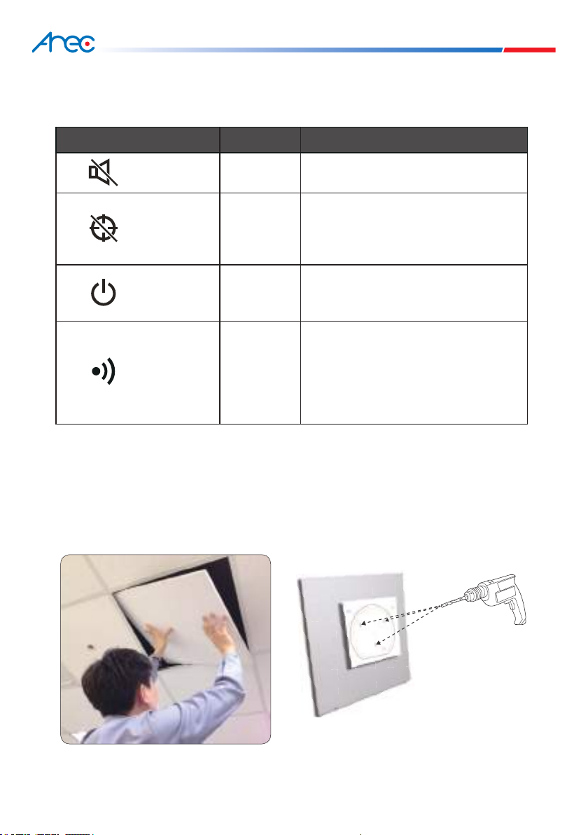
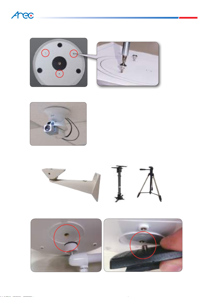
10. Please wire your product according to the installation guide and instructions printed on your product for
the optimal effect.
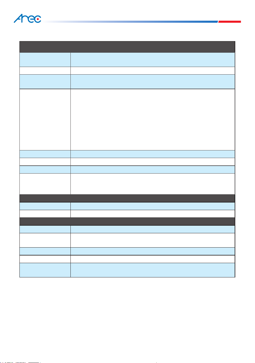
Safety precautions