AEG Protect PV Manual de usuario

Protect PV - Solar Inverters
User Manual
AEG Power Solutions GmbH
Revision: 01
Date: 2011-05-25
UserManual
8000038784_00_BAL_en

Contents
1. Introduction 2
Introduction 2
Operation Mode Definition 2
2. Display 4
Display 4
View 5
View 2 5
Status 6
Production Log 8
Setup 10
3. Web Server Quick Guide 12
Introduction 12
Supported Characters 12
Access and Initial Setup 12
Setup Wizard 13
Operation 17
Web Server Structure 17
Plant, Group and Inverter Views 19
Additional Information 20
4. Troubleshooting 21
Troubleshooting 21
5. Maintenance 22
Maintenance 22
Cleaning the Cabinet 22
Cleaning the Heatsink 22
Contents
8000038784_00_BAL_en / L00410565-01_02 1

1. Introduction
1.1. Introduction
This manual provides information on functionality and maintenance of the Protect PV solar in-
verter.
Illustration 1.1: Protect PV 10 kW, Protect PV 12.5 kW, Protect PV 15 kW
CE marking - This certifies the conformity of the equipment with the regula-
tions which apply in accordance with the directives 2004/108/EC and
2006/95/EC.
The Protect PV inverter series comprises:
Protect PV
Protect PV easy
1.2. Operation Mode Definition
Off grid (LEDs off)
When no power has been delivered to the AC grid for more than 10 minutes, the inverter dis-
connects from the grid and shuts down. This is the normal night mode. The user and communi-
cation interfaces are still powered for communication purposes.
Connecting (Green LED flashing)
The inverter starts up when the PV input voltage reaches 250 V. The inverter performs a series
of internal self-tests, including PV auto detection and measurement of the resistance between
the PV arrays and earth. Meanwhile, it also monitors the grid parameters. When the grid pa-
rameters have been within the specifications for the required amount of time (depends on
country settings), the inverter starts to energise the grid.
1. Introduction
2 8000038784_00_BAL_en / L00410565-01_02
1

On grid (Green LED on)
The inverter is connected to the grid and energises the grid. The inverter disconnects if: It de-
tects abnormal grid conditions (depending on country settings), if an internal event occurs or if
no PV power is available (no power is supplied to the grid for 10 minutes). It then goes into
connecting mode or off grid mode.
Fail Safe (Red LED flashing)
If the inverter detects an error in its circuits during the self-test (in connecting mode) or during
operation, the inverter goes into fail safe mode. The inverter will remain in fail safe mode until
PV power has been absent for a minimum of 10 minutes, or the inverter has been shut down
completely (AC + PV).
Refer to the section on
Troubleshooting
for further information.
1. Introduction
8000038784_00_BAL_en / L00410565-01_02 3
1
2. Display
2.1. Display
Note:
Due to the advanced functionalities of the inverter, it may take up to 10 seconds before the
display becomes available after power up.
The integrated display on the inverter front gives the user access to all information about the
PV system and the inverter.
The display has two modes:
Normal The display is in use
Power saving After 10 min. of no display activity the back light of the display turns off to save power.
Re-activate the display by pressing any key
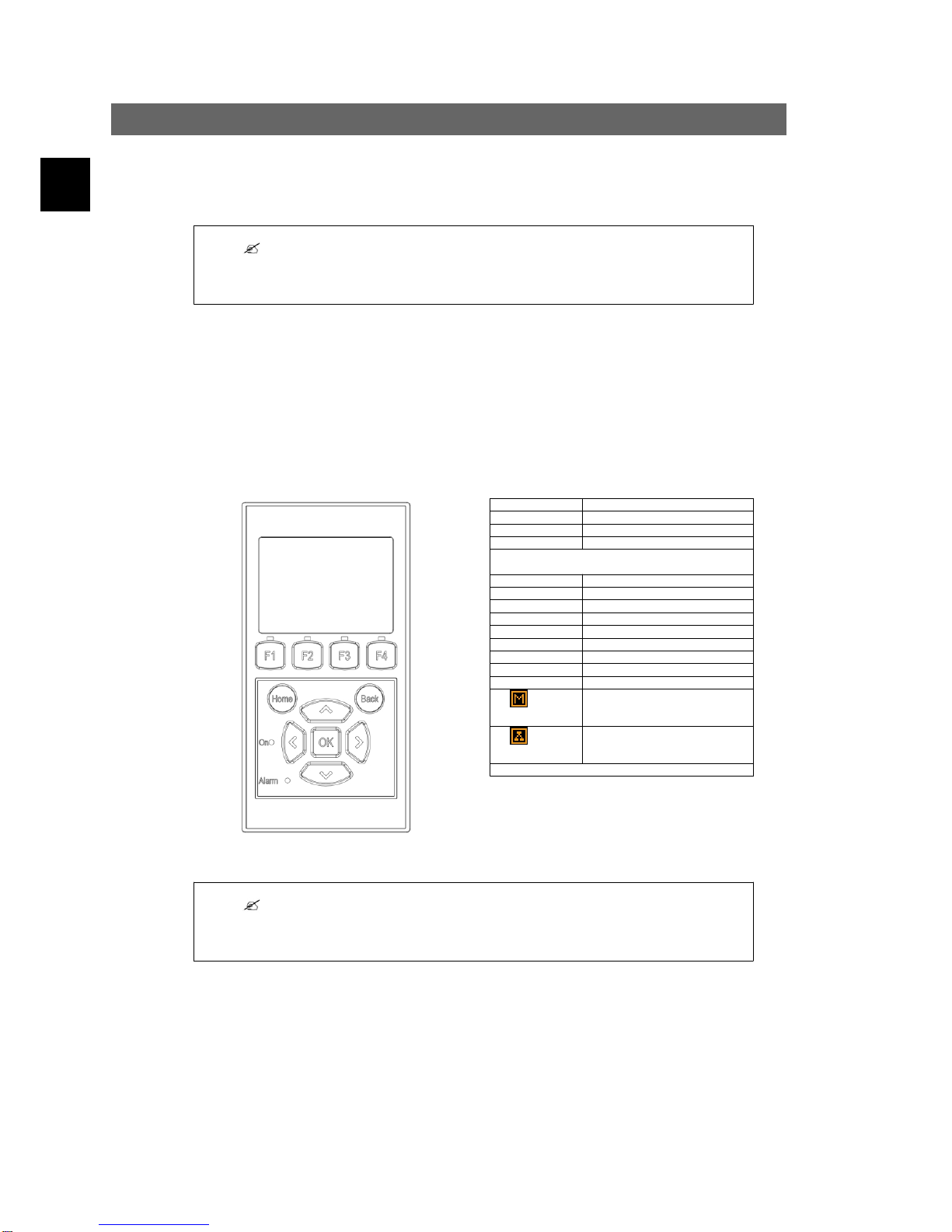
Overview of display buttons and functionality:
Illustration 2.1: Display
F1 View 1 / View 2 - Screen
F2 Status Menu
F3 Production Log Menu
F4 Setup Menu
* When an F-key is selected the LED above it will light
up.
Home Return to View Screen
OK Enter/select
Arrow up A step up/increase value
Arrow Down A step down/decrease value
Arrow Right Moves cursor right
Arrow Left Moves cursor left
Back Return/de-select
On - Green LED On/flashing = On grid/Connecting
Alarm - Red LED Flashing = Fail safe
The inverter is configured as mas-
ter. Icons can be found in the top
right corner.*
The inverter is connected to a mas-
ter. Icons can be found in the top
right corner.*
*) Protect PV easy only.
Note:
The contrast level of the display can be altered by pressing the arrow up/down button while
holding down the F1 button.
The menu structure is divided into four main sections:
View Presents a short list of information, read only.
Status Shows inverter parameter readings, read only.
Production Log Shows logged data.
Setup Shows configurable parameters, read/write.
See the following sections for more detailed information.
2. Display
4 8000038784_00_BAL_en / L00410565-01_02
2
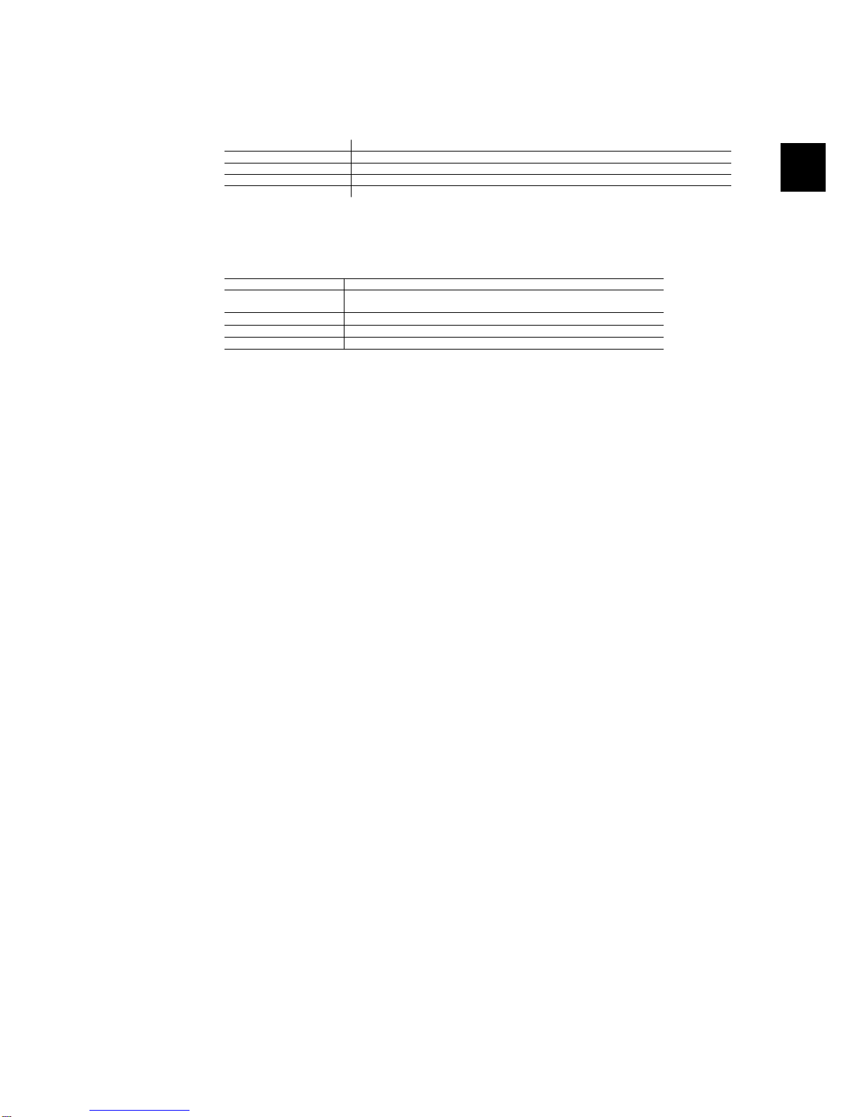
2.1.1. View
Menu Structure - View
Parameter Description
Mode: On grid Displays present inverter mode. See operation mode definitions
Prod. today: 12345 kWh Energy production today in kWh. Value from inverter or S0 energy-meter
Output Power: 12345 W Current output power in Watt
[ --- utilization bar --- ] Shows level of inverter utilisation as % of max. utilisation
Table 2.1: View
2.1.2. View 2
Menu Structure - View 2
Parameter Description
Grid mgmt: Indicates whether or not any grid management measures are in effect.
Hidden if no grid management measures are in effect.
Performance ratio: 87 %*Performance ratio is shown if irradiation sensor is available (local or master).
Total CO2 saved:123 T*Lifetime CO2 emission saved, calculated using configured value.
Total revenue: 234.5 Euro *Lifetime revenue, calculated using configured value.
Table 2.2: View 2
*) Not available.
2. Display
8000038784_00_BAL_en / L00410565-01_02 5
2
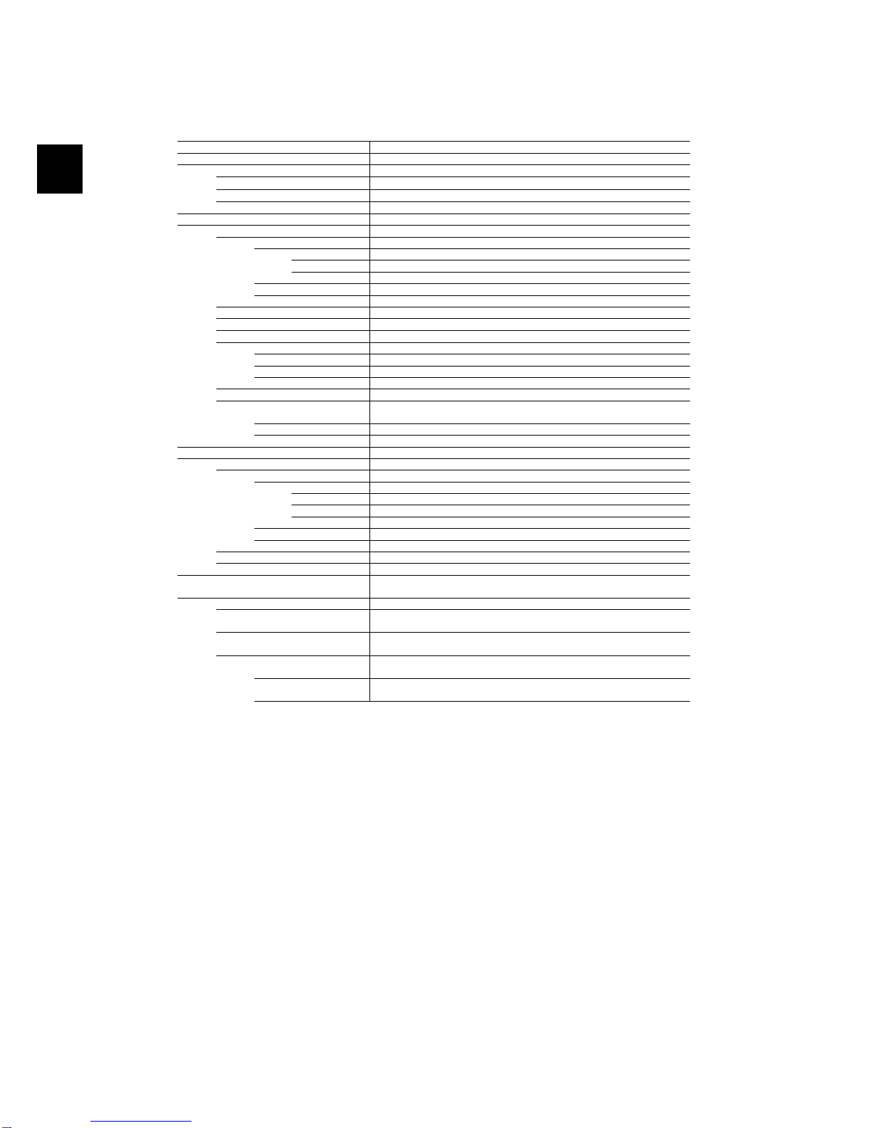
2.1.3. Status
Menu Structure - Status
Display Functions Description
[-] Ambient Conditions Only applicable if sensors are connected
Irradiance: 1400W/m2Irradiance. “NC” if not connected
PV module temp: 100 oCPV module temperature. “NC” if not connected
Ambient temp: 20 oCAmbient temperature. “NC” if not connected
Irr. sensor temp: 20 oCIrradiation sensor temperature. “NC” if not connected
[-] Photovoltaic
[-] Present values
[-] PV input 1
Voltage: 1000V Voltage detected at PV input 1
Current: 15.0 A Current detected at PV input 1
Power 10000 W Power detected at PV input 1
[+] PV input 2
[+] PV input 3 Not visible if inverter type is 10 kW
[-] Isolation Resistance
Resistance: 45 MΩPV isolation at start up
[-] PV Input Energy
Total: 369000kWh Daily production of all PV inputs
PV1: 123000 kWh Daily production of PV input 1
PV2: 123000 kWh Daily production of PV input 2
PV3: 123000 kWh Daily production of PV input 3
[-] PV Configuration
PV input 1: Individual Configuration of PV input 1. The configuration is only shown when the in-
verter is in Connecting or On grid mode.
PV input 2: Individual
PV input 3: Individual
[-] AC-grid
[-] Present Values
[-] Phase 1
Voltage: 250 V Voltage on phase 1
Current: 11.5 A Current on phase 1
Frequency: 50 Hz Frequency on phase 1
Power: 4997 W Power on phase 1
[+] Phase 2
[+] Phase 3
[-] Residual Current Monitor
Current: 350 mA Residual current in mA
[-] Grid management Only visible if the inverter is set up for feed-in to medium or high voltage
grid (e.g. _MV country is the selected country)
[-] Power level adjustment
[-] Present limit: 100 % Maximum allowed power output in % of nominal power output. “Off”
means that the power level functionality has been disabled in the inverter.
[-] Reactive power Only displayed if the current country setting is an MV country or custom,
and in Protect PV versions.
Setpoint type: Off The setpoint type for Reactive Power. Off means that no internal setpoints
are used, but the inverter will accept an external setpoint.
Value: - The current value of the setpoint for reactive power, the unit depends on
the selected setpoint type.
Table 2.3: Status
2. Display
6 8000038784_00_BAL_en / L00410565-01_02
2
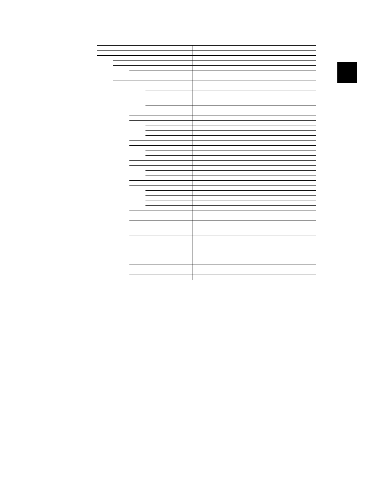
Menu Structure - Status - Continued
Display Functions Description
[-] Inverter
[-] Country: Germany Country setting
[-] Internal Conditions
Power module 1: 100 oCTemperature detected at the power module
PCB1 (AUX): 100 oCTemperature detected internally
[-] Serial no. and SW ver.
[-] Inverter
Prod- and serial number:
A0010000201 Inverter product number
011900H2304 Inverter serial number
Software version: Inverter software version
MAC address: The MAC address of the communication board
...
[-] Control board
Part - and serial number:
C00100003111 Control board part number
022500H2004 Control board serial number
Software version: Control board software version
[-] Power board
Part - and serial number:
C00100004529 Power board part number
0023600H2104 Power board serial number
[-] AUX board
Part - and serial number:
C0010000241 Aux board part number
002541H2204 Aux board serial number
[-] Communication board
Part - and serial number:
C0010000201 Communication board part number
032500H2504 Communication board serial number
Software version: Communication board software version
[-] Func. Safety Processor
Software version: Functional Safety processor software version
[-] Display
Software version: Display software version
[-] Upload status
Upload status: Off Current upload status
Signal strength: 99 Signal strength. Should preferably be between 16-31. 99 Indicates
no signal
GSM status: None Current GSM network status
Network: Network to which the modem is connected
Failed uploads: 0 Number of consecutive failed uploads
Last error: 0 Last error ID, please see the GSM manual for further assistance
- Time and date of last error
Last upload:
- Time and date of last successful upload
Table 2.4: Status - Continued
2. Display
8000038784_00_BAL_en / L00410565-01_02 7
2
2.1.4. Production Log
Menu Structure - Production Log
Display Functions Description
Total production:
123456 kWh Total production since installation of inverter
Total operating time:
20 hours Total operating time since installation of inverter
[-] Production log
[-] This week Production from this week
Monday: 37 kWh Production from one day shown in KWh
Tuesday: 67 kWh
Wednesday: 47 kWh
Thursday: 21 kWh
Friday: 32 kWh
Saturday: 38 kWh
Sunday: 34 kWh
[-] Past 4 weeks
This week: 250 kWh Production from this week shown in KWh
Last Week: 251 KWh
2 Weeks ago: 254 KWh
3 Weeks ago: 458 KWh
4 Weeks ago: 254 KWh
[-] This year
January: 1000 kWh Production from one month shown in kWh
February: 1252 KWh
March: 1254 KWh
April: 1654 KWh
May: 1584 KWh
June: 1587 KWh
July: 1687 KWh
August: 1685 KWh
September: 1587 KWh
October: 1698 KWh
November: 1247 KWh
December: 1247 KWh
[-] Past years Yearly production, up to 20 years back
This year: 10000 kWh Production from this year shown in KWh
Last year: 10000 kWh/m2
2 years ago: 10000 kWh/m2
3 years ago: 10000 kWh/m2
...
20 years ago: 10000 kWh/m2
[-] Irradiation log Only visible if it contains non-zero values
[-] This week Irradiation from this week
Monday: 37 kWh/m2Irradiation from one day shown in kWh/m2
Tuesday: 45 kWh/m2
Wednesday: 79 kWh/m2
Thursday: 65 kWh/m2
Friday: 88 kWh/m2
Saturday: 76 kWh/m2
Sunday: 77 kWh/m2
[-] Past 4 weeks Irradiation from this week shown in kWh/m2
This week: 250 kWh/m2
Last week: 320 kWh/m2
2 weeks ago: 450 kWh/m2
3 weeks ago: 421 kWh/m2
4 weeks ago: 483 kWh/m2
[-] This year
January: 1000 kWh/m2Irradiation from one month shown in kWh/m2
February: 1000 kWh/m2
March: 1000 kWh/m2
April: 1000 kWh/m2
May: 1000 kWh/m2
June: 1000 kWh/m2
July: 1000 kWh/m2
August: 1000 kWh/m2
September: 1000 kWh/m2
October: 1000 kWh/m2
November: 1000 kWh/m2
December: 1000 kWh/m2
[- ] Past years Yearly irradiation up to 20 years back are shown
This year: 10000 kWh/m2
Last year: 10000 kWh/m2
2 years ago: 10000 kWh/m2
3 years ago: 10000 kWh/m2
...
20 years ago: 10000 kWh/m2
Table 2.5: Production Log
2. Display
8 8000038784_00_BAL_en / L00410565-01_02
2

Menu Structure - Production Log - Continued
Display Functions Description
[-] Time stamps
Installed: 31-12-07 Date of first grid connection
Power down: 21:00:00 When the inverter was last connected to grid
Prod. initiated: 06:00:00 When the inverter first connected to grid today
[-] De-rating
Total de-rate: 0 h Period of time the inverter has limited power production in total, shown in
hours
Pwr level adjust: 0 h Due to Power level adjustment
Freq. stabiliza.: 0 h Due to frequency support
Reactive Power: 0 h Due to reactive energy support
[-] Reactive Power Only visible if the current country setting is an MV country or custom, and in
Protect PV versions.
[-] Reactive Energy (underexcited):
1000 000 VArh
[-] Reactive Energy (overexcited):
1000 000 VArh
[-] Event log
Latest event:
0
The latest event is displayed. The number is for service purposes
Zero indicates no error.
[-] Last 20 events The latest 20 events are displayed
1 : 29-01-2009 14:33:28 Date and time of the event
Grid 29 off Group - ID - Status of the event
2 : 29-01-2009 14:33:27
Grid 29 on
-
20:
Table 2.6: Production Log - Continued
2. Display
8000038784_00_BAL_en / L00410565-01_02 9
2
Otros manuales para Protect PV
1
Este manual sirve para los siguientes modelos
4
Tabla de contenidos
Otros manuales de Inversor de AEG

AEG
AEG Si 150 Manual de usuario

AEG
AEG AS-IC01-4000 Manual de usuario

AEG
AEG SW 2000 Manual de usuario

AEG
AEG AGN6500 Manual de usuario

AEG
AEG AS-IR01 Manual de usuario

AEG
AEG 1000 W Manual de usuario

AEG
AEG Protect PV 2800 Manual de usuario

AEG
AEG AS-IC01-4000-2 Manual de usuario

AEG
AEG AS-IR02 Series Manual de usuario

AEG
AEG AS-ICH02-2/HV Series Manual de usuario


