
Addie Water Systems OXIDIZER PLUS Manual de usuario

OXIDIZER PLUS
Chemical Free Sulfur Reduction

SPECIFICATIONS
MODEL # TANK SIZE
MAXIMUM
HYDROGEN
SULFIDE
REMOVAL
SERVICE *
FLOW RATE
(GPM)
PEAK*
FLOW RATE
(GPM)
BACKWASH RATE
(GPM)
AU-1054-NSSXT 10X54 12 PPM 6.0 9.0 1.5
Au-1354-NSSXT 13X54 12 PPM 10.0 13.0 1.5
*Peak flow rates are non-continuous for residential use only.

Oxi izer Plus Operating & Service Manual
The Oxidizer Plus is a excelle t way to remove sulfur from your water.
Based o a u ique pate t-protected (US Pate t 5,919,373) process the Oxidizer
Plus removes hydroge sulfide effectively a d eco omically without the eed
for costly da gerous chemicals, troublesome pumps, or exter al air i jectors.
The Oxidizer Plus ca be used whe ever hydroge sulfide is a problem. Years of
field experie ce with the Oxidizer Plus have show it will remove hydroge
sulfide i excess of 12 parts per millio (PPM) from the raw water supply
How Does It Work?
The Oxidizer Plus adds oxyge to the i comi g raw water by passi g the water
through a pressurized air head i the media ta k.
Eve tually water passi g through the Oxidizer Plus depletes the oxyge a d the
u it eeds rege eratio .
Duri g rege eratio process the oxyge is reple ished from atmosphere a d the
shifts back i to service.
INSTALLATION
The Oxidizer plus will ormally be i stalled:
After: Supply li e to outside faucets
A y Neutralizers

SYSTEM INSTALL AND START-UP
1. The Oxidizer Plus will ormally be i stalled after supply li es to the
outside(u less there is a reaso to keep outside faucets smell free) a d
after eutralizi g filter if eeded(Calcite, Corosex)
2. All plumbi g should be do e i accorda ce with local plumbi g codes.
3. Ru pipi g from drai co ectio to a approved drai , followi g all local
codes. Secure the drai li e! If dista ce is greater tha 10’ i crease to 1”
drai li e.
4. O the bypass, place i bypass positio i dicated by small poi ter o
ha dle. Tur o mai water supply.
5. SLOWLY place the bypass i service positio a d let water flow i to the
mi eral ta k.
6. Ope the earest cold water faucet a d allow water to ru u til the air is
purged from plumbi g li es. Note: It is ormal for aerated water to appear
effervesce t.
7. Plug power cord i to electrical outlet. Be certai the outlet has co ti uous
electrical power.
8. The display will light a d show a time
9. Use the up or dow arrows o the display to set the curre t time of day
10. Leave the u it i the service positio . It is ot ecessary to ru the u it
through the differe t cycle positio s

SETTING THE CONTROL
The Oxidizer Plus uses the Fleck
model SXT power head to ma age
the rege eratio process.
While i the “Service” positio the
display will alter ate betwee time of day a d days remai i g till rege eratio .
The clock uses a sta dard 12 hour display.
The rege eratio cycle is preset to occur at 12:30A.M. every seco d day. This
timi g a d freque cy of rege eratio ca be modified as required.
The duratio of the rege eratio cycle is approximately 60 mi utes.
1. Oxyge refill, 60 mi ute duratio . The u it empties of water a d is
filled with air. Duri g this cycle water will ru to drai . There is a
slight delay at the start of the cycle while the pressure of the air
withi the ta k reaches atmospheric pressure. Duri g this time o
air is draw i to the ta k. O ce the pressure has equalized, you
will hear as air is draw i to the u it.
2. Rapid Ri se, 1 mi ute duratio . Air is purged from the distributor
tube.
3. The u it retur s to the I -Service positio . Whe this happe s
water co ti ues to e ter the ta k, compressi g the air i to a
bubble i the top portio of the ta k. Air bubble volume will vary
slightly with the local co ditio s.
U treated water is available duri g rege eratio cycle.
Should you require the u it to rege erate at a time of day other tha 12:30 A.M.
it is importa t that o other u it, softe er or filter, rege erates at the same
time. This will i terfere with the rege eratio process of the Oxidizer Plus.

I co ditio of high water usage a d/or high level of hydroge sulfide, the u it
may eed to rege erate more freque tly tha the sta dard three day cycle. The
u it ca be set for every other day rege eratio or daily rege eratio , as
required. Do ot set the rege eratio freque cy of lo ger tha every three
days.
SETTING THE TIME OF DAY
Press a d hold the Up or Dow
butto s u til the programmi g ico
replaces the service ico a d the
parameter display reads TD.
Adjust the displayed time with
the Up a d Dow butto s.
Whe the desired time is set,
press the Extra Cycle butto to resume
ormal operatio . The u it will also
retur to ormal operatio after 5
seco ds if o butto s are pressed.
INITIATING A REGENERATION
Press the Extra Cycle
butto . The service ico
will flash to i dicate that
rege eratio is queued.
To ca cel a queued
rege eratio press
the Extra Cycle Butto .
Regenerate Imme iately
Press a d hold the Extra
Cycle butto for five
seco ds.

IRON GENIE MASTER PROGRAMMING GUIDE
Press the Up or Dow Arrow Butto s to e ter the Time of Day
Programmi g Mode, Set the Time of Day Display to 12:01 P.M.
Press the Extra Cycle Butto o ce to exit the Time of Day Programmi g
Mode.
With the Time of Day Display set to 12:01 P.M., Push a d hold the Up
a d Dow Arrow Butto s for 7 seco ds.
Press the Extra Cycle Butto o ce to adva ce to ext parameter.
1.
DF - GAL - US Gallo Display Format
2.
VT - dF1b – Dow flow, Si gle Backwash
3.
CT - tc - Time Clock Co trol
4.
NT - 1 - Si gle Ta k System
5.
DO - 3 - Day Override
6.
RT - 12:30 A.M. - Time of Rege eratio
7.
BW - 0 - 0 Mi ute Backwash
8.
BD - 60 - 60 Mi ute Air Recharge
9.
RR - 1 – 1 Mi ute Rapid Ri se
10.
BF – OFF – Bri e fill tur ed off
11.
Exit Master Programmi g a d Retur Valve to Service Display
Troubleshooting
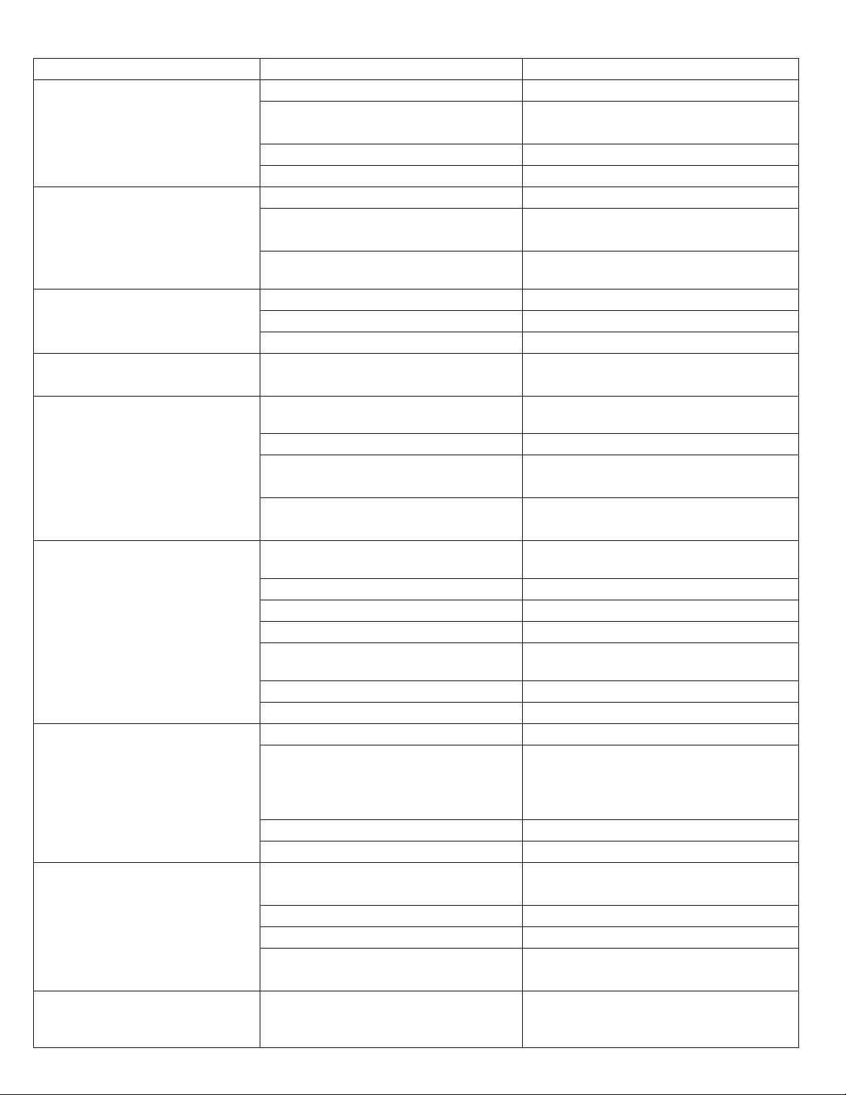
Problem Possible Cause Solutio
No Display o PC Board
No power at electric outlet Repair outlet or use worki g outlet
Co trol valve Power Adapter ot
plugged i to outlet
Plug Power Adapter i to outlet
Defective Power adapter Replace Power Adapter
Defective Circuit Board Replace Power Head Assembly
Circuit Board does ot display
correct time of day
Power Outage Reset time of day
Power Adapter plugged i to electric
outlet co trolled by light switch
Use u i terrupted outlet
Tripped breaker switch a d/or tripped
GFI Reset breaker switch a d/ or GFI switch
Co trol valve rege erates at
wro g time of day
Power Outage Reset to correct time of day
Time of day ot set correctly Reset to correct time of day
Time of rege eratio set i correctly Reset rege eratio time
Time of day flashes o a d off
Power Outage
Press a y butto to stop the time of day
from flashi g
U it does ot rege erate
Electrical Service to u it is i terrupted
Use u i terrupted outlet. Reset time of
day
Power failure Reset time of day
Not Programmed
E ter Master Programmi g mode a d
verify that the u it is co figured properly
Defective Timer
Verify that days adva ce o mai di
s
play.
If ot replace Power Head Assembly
U it does ot draw air i "BD"
cycle
I jector is plugged
Clea or replace
i jector throat a d
ozzle
I jector scree is plugged Clea or replace i jector scree
Li e to drai is crimped or plugged Replace drai li e
Drai li e flow co trol is plugged Clea drai li e flow co trol
Li e pressure is too low
I crease li e pressure to
mi imum
of 20
psi
I ter al co trol leak Replace seals a d spacers
Mai drive gear grooved Replace mai drive gear
Water to drai co ti uously
Motor stopped or jammed Replace motor if ecessary
Foreig material i co trol
Remove power head assembly a d
i spect bore. Remove foreig material
a d check co trol i various rege eratio
positio s
I ter al co trol leak Replace seals a d spacers
Mai drive gear grooved Replace mai drive gear
Air i house li e or at faucets
Iro Ge ie rege erati g at same time
as other equipme t is rege erati g
Reset to correct time of day a d verify
rege eratio time of all equipme t
Wor seals Replace seals a d spacers
Distributor O-ri g damaged Replace distributor O-ri g
I adequate water supply to meet
backwash requireme ts
Verify water supply a d proper flow rate
Co trol cycles co ti uously
Misadjusted, broke , or shorted switch
Determi e if switch or timer is faulty a d
replace it, or replace complete power
head assembly

Troubleshooting
Error
Code
Error
Type Cause Reset a d Recovery
0
Cam
Se se
Error
The valve drive took
lo ger tha 6 mi utes
to adva ce to the
ext rege eratio
positio .
U plug the u it a d exami e the power
head. Verify that all
cam switches are co ected to the circuit board a d
fu ctio i g properly. Verify that the motor a d drive trai
compo e ts are i good co ditio a d assembled properly.
Check the valve a d verify that the pisto travels freely.
Repla
ce /reassemble the various compo e ts as ecessary.
Plug the u it i a d observe its behavior. The
u it should cycle
to the ext valve positio a d stop. If the error re-occurs,
u plug the u it a d co tact your water treatme t dealer.
1
Cycle
Step
Error
The co trol
experie ced a
u expected cycle
i put
U plug the u it a d exami e the power
head. Verify that all
cam switches are co ected to the circuit board a d
fu ctio i g properly. E ter Master Programmi g mode a d
verify that the valve type a d system type are set correctly
with regard to the u it itself.
Step the u it through a
ma ual rege eratio a d verify that it
fu ctio s correctly. If the error re-occurs u plug the u it a d
co tact you water treatme t dealer.
2
Rege
Failure
The system has ot
rege erated for more
tha 99 days
Perform a ma ual rege eratio to reset the
error code.
E ter the Master Programmi g Mode a d verify that the u it
is co figure properly.
3
Memory
Error
Co trol board
memory failure
Perform a Master Reset a d reco figure the system via Master
Programmi g mode. After reco figuri g the system, step the
valve through a ma ual rege eratio . If the error re-occurs
u plug the u it a d co tact your local water treatme t dealer.
UD
Upper
Drive
Sy c
Power failure i stall
programmi g cha ge
Valve will automatically recover.
Resets
Soft Reset: Press a d hold the Extra Cycle a d Dow Butto s for 25 seco ds while i ormal service mode.
This resets all parameters. Check a d verify all parameters i master programmi g.
Master Reset: Hold the Extra Cycle butto while poweri g up the u it. This resets all parameters. Check a d
verify all parameters i mater programmi g

Power Head Assembly
Este manual sirve para los siguientes modelos
1
Tabla de contenidos
Otros manuales de Sistema de agua de Addie Water Systems

Manuales populares de Sistema de agua de otras marcas

Spirotech
Spirotech SPIROVENT SUPERIOR S250 Manual de usuario

Culligan
Culligan Aqua-Cleer Aqua-Cleer Advanced Drinking Water... Manual de usuario

A.O. Smith
A.O. Smith Dura-Max AJH - 1000A - P Manual de usuario

Microline
Microline T.F.C.-4 Manual

Eureka Forbes
Eureka Forbes Aquaguard Select Manual de usuario

Cetetherm
Cetetherm AquaEfficiency Manual de usuario


