Abus PPIC46520 Manual de usuario

1
WLAN LIGHT UDENDØRS KAMERA
W I - F I L I G H T O U T D O O R C A M E R A
QUICK GUIDE
PPIC46520 V 1.0

2
SYSTEMKRAV
SYSTEM REQUIREMENTS
Netværk uden kryptering understøttes ikke.
Networks without encryption are not supported.
Aktivér "placeringstjenesten" (f.eks. "GPS") på din smartphone eller tablet, som du udfører
ibrugtagningenmed. Denne skal bruges senere til at vise netværkene i området.
Activate the "location service" (e.g. "GPS") of your smartphone or tablet with which you
carry out start-up. This will be needed later to display the networks in the vicinity.
WLAN-netværk med adgangskode og kryptering.
WLAN-adgangskoden må ikke overstige 31 tegn.
Wi-Fi network with password and encryption.
The Wi-Fi password must not exceed 31 characters.
Placeringstjenesten på den mobile slutenhed skal være aktiveret.
The location service of the mobile device must be activated.
Bluetooth på den mobile slutenhed skal være aktiveret.
Bluetooth must be activated on the mobile device.
Kameraet kan kun bruges sammen med App2Cam Plus-appen.
The camera can only be used in conjunction with the App2Cam Plus app.
Følgende specialtegn understøttes, når du indtaster WLAN-adgangskoden.
The following special characters are supported when entering the Wi-Fi password.
Når du indtaster WLAN-adgangskoden, er følgende specialtegn ikke mulige.
When entering the Wi-Fi password, the following special characters are not possible.

3
ABUS WLAN Light udendørs kamera (PPIC46520)
ABUS Wi-Fi Light Outdoor Camera (PPIC46520)
LEVERINGSOMFANG
SCOPE OF DELIVERY
Information
Information
1
microSD-kort
(forudinstalleret)
microSD card
(preinstalled)
Unbrakonøgle
Allen key
Monteringsmateriale
Mounting material
Kamerafod
Camera Base
Boreskabelon
Drill template
Hjælp til at erne
microSD-kortet
Removal aid
for the microSD card
WLAN Light udendørs kamera
Wi-Fi Light Outdoor Camera
Antenne
Antenna
1
1
1
1
1
11
1
USB-A til USB-C-kabel
USB-A to USB-C cable
1

4
KAMERA
CAMERA
Forside
Front
Mikrofon
Microphone
Låseskrue til kamerafod
Camera base screw
Objektiv
Lens
Hvidlys-LED
White light LED
Lyssensor
Light sensor

5
Bagside
Rear
Antennetilslutning (RP-SMA)
Antenna connection (RP-SMA)
Åbninger til
LAN-forbindelse
Openings for
LAN connection
Åbninger til
fastgørelsesskruer
Openings for
mounting screws
Åbning til 230 V-kabel
Opening for 230 V cable
6
Til videooptagelser er kameraet udstyret med et microSD-kort fra fabrikken. Hvis du ikke bruger ring-buf-
fer-funktionen eller har brug for mere lagerplads, kan du udskie det med et almindeligt microSD-kort
(maks. 128 GB, min. klasse 10). Det vedlagte værktøj er beregnet til at erne det. For at erne og indsætte-
hukommelseskortet skal kameraet være arudt fra strømforsyningen. Når microSD-kortet er sat i,kan man
høre, at det klikker på plads.
The camera is factory-equipped with a microSD card for video recordings. If you do not use the ring
memory function or need more storage space, you can replace it with a commercially available
microSDcard (max. 128 GB, min. class 10). The provided removal tool can be used to remove the card.
The camera must be disconnected from the power supply to remove and insert the memory card.
When inserted, the mircoSD card audibly clicks into place.
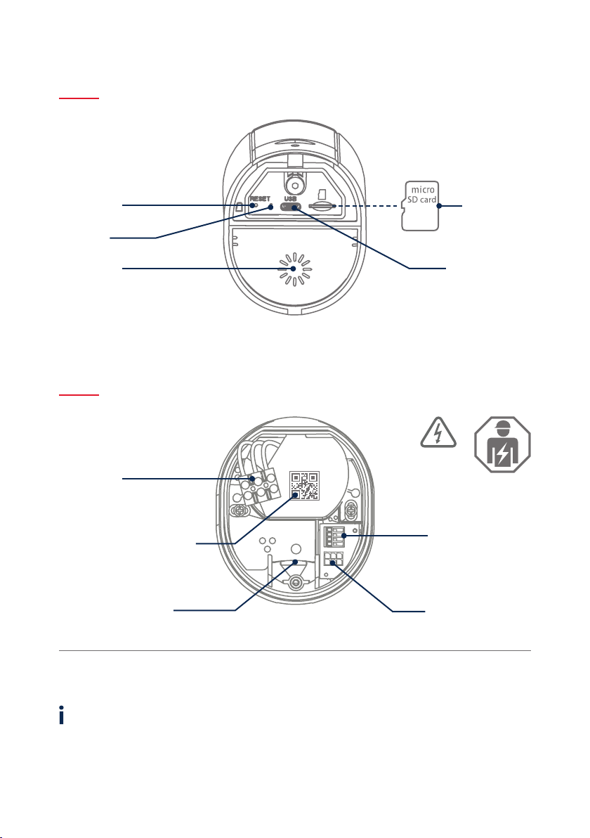
Underside (åben afdækning)
Underside (open cover)
Kamerafod (indvendigt)
Camera base (inside)
microSD-kort
microSD card
USB-C-tilslutning
USB-C port
Højtaler
Loudspeaker
Reset-tast
Reset button
Status-LED
Spændingsforsyning
(230 V AC)
Power supply
(230V AC)
QR-kode og registreringsnummer
til kameraverikation
QR code and identication
number for camera verication
1/2/3/6: Tilslutning til
LAN-interface
1/2/3/6: LAN interface
connection
Parkeringsposition for
kamera under montering
Park position for camera
during mounting
Strømkabel til kameraet
(tilslutningsblok)
Power cable to camera
(connection block)
VIGTIGT!
IMPORTANT!

7
Hvis der opstår problemer under ibrugtagningen, eller
hvis du har glemt adgangsdataene (adgangskode og
sikkerhedskode), skal du nulstille kameraet til fabrik-
sindstillingerne:
Åbn kameraets bunddæksel med en unbrakonøgle, og
trykpå reset-tasten i mindst 5 sekunder med en tynd
genstand(f.eks. værktøjet til ernelse af microSD-kort
eller en papirclips), indtil status-LED'en blinker.
If there are any diiculties during start-up or if you have
forgotten the access data (password and security code),
reset the camera to factory settings:
Open the bottom cover of the camera using an Allen key
and press the reset button for at least 5 seconds using a
thin object (e.g. the microSD card removal tool or a paper
clip) until the status LED ashes.
FABRIKSINDSTILLINGER
FACTORY RESET
Kameraet kan tages i brug via appen før installationen.
Fordel: På denne måde kan du allerede se det første live-
billede og njustere kameraets synsretning direkte under
den følgende montering. Under ibrugtagningen skal du
bruge det medfølgende USB-kabel til midlertidig strømfor-
syning og bruge et standard smartphone-opladningsstik
(5V, 1 A). Tilslut den til det tilsvarende stik på kameraet;
det sidder på undersiden af kameraet bag dækslet.
The camera can be set up using the app before installation.
Advantages: You can then already see the rst live image
and ne-tune the camera’s viewing direction directly
during subsequent installation. During start-up, use the
enclosed USB cable for temporary power supply and use a
standard smartphone charging plug (5 V, 1 A). Connect it to
the corresponding connector on the camera; this is located
on the underside of the camera behind the cover.
MIDLERTIDIG STRØMFORSYNING
TEMPORARY POWER SUPPLY

8
MONTERING AF KAMERA
CAMERA INSTALLATION
Marker placeringen af de nødvendige borehuller ved hjælp af boreska-
belonen, bor hullerne, og indsæt dyvlerne.
Using the drilling template, mark the position of the required
drill holes, drill the holes and insert the dowels.
2
Ved installationen af apparatet drejer det sig om arbejde ved netspæn-
dingen. Den skal derfor udføres af en fagmand i overensstemmelse
med de installationsforskrier og tilslutningsbetingelser, der gælder
i landet. Under monteringen skal ledningen, der skal tilsluttes, være
arudt fra netspændingen. Derfor skal du som det første slukke for
strømmen. Sørg for, at eektaryderen forbliver slukket under hele
installationen. Sørg om muligt for, at denne eektaryder ikke er til-
gængelig. Dereer skal det fastslås med et egnet måleinstrument, at
der ikke er spænding ved polerne.
Installation of the device involves work on the mains power supply.
It must therefore be carried out by a specialist in accordance with
the national installation regulations and connection requirements.
Electrical wires must be disconnected from the power supply during
installation. Therefore, switch o the power rst. Make sure that the
circuit breaker remains switched o during the entire installation
process. If possible, ensure that this circuit breaker is not accessible.
Aerwards, determine the absence of voltage at all poles using a
suitable measuring device.
1
OFF
VIGTIGT!
IMPORTANT!
Der er tre små åbninger på bagsiden af kamerafoden til de tre ledere
i strømkablet, som skal forsyne kameraet med spænding. Før de tre
ledere gennem gummipakningen på de relevante steder. Sørg for, at
kabellængden passer til den følgende tilslutning til klemrækken i bes-
lagets fod. Monter beslagets fod i den planlagte kameraposition med
de medfølgende skruer.
On the back of the camera base, three small holes are indicated for the
three wires of the power cable that is supposed to supply the camera
with regular voltage. Feed the three wires through the rubber seal at
the through the rubber seal at the corresponding points. Make sure
that the cable length is suitable for the following connection to the
screw terminal block in the base of the mount. Install the base of the
mount in the intended camera position using the supplied screws.
3

9
Tag nu kameraet, som er forbundet med et strømkabel, ud af parke-
ringspositionen, og skru det fast på beslagets bund. Sørg for, at ingen
kabler kommer i klemme.
Now take the camera connected by power cable out of the parking
position and screw it back onto the base of the mount. Make sure
that no cables are pinched.
7
5
Beslagets fod har en såkaldt parkeringsposition til kameraet.
Sæt kameraet i parkeringsposition til følgende ledningsføring.
The base of the mount has a so-called parking position for the camera.
Place the camera in the parking position for the following cabling.
4Forbind strømførende leder, neutral leder og beskyttelsesleder,
der tidligere er ført gennem foden, med klemrækken.
Tip: Klemrækken kan ernes fra sit beslag.
L = strømførende ledning (oest sort eller brun)
N = neutralleder (oest blå)
= beskyttelsesleder (grøn-gul)
Connect the live conductor, neutral conductor and the PE conductor that
were previously passed through the base to the screw terminal block.
Tip: The screw terminal block can be removed from its holder.
L = Live conductor (usually black or brown)
N = Neutral conductor (usually blue)
= Protective earth conductor (green-yellow)
6Vigtigt! Tilslut den (grøn-gule) beskyttelsesleder, som allerede er sluttet
til fodens afdækning fra fabrikken, til klemrækken i kamerafoden. Ved
behov: Brug den lille styreskinne i kamerafoden til lederen. Tilslut deref-
ter kameraets strømkabel korrekt via det (sorte) stik til den tilsvarende
tilslutning i kamerafoden. Bemærk: Stikket er gået i hak i den korrekte
position for at forhindre utilsigtet frakobling under yderligere monte-
ring. Ved afmontering skal du tage hensyn til den passende klemmeme-
kanisme for ikke at beskadige ledningerne.
Important! Connect the (green-yellow) protective earth conductor,
which is already connected to the cover of the foot ex factory, to the
terminal block in the camera foot. If necessary: Use the small wire rail
in the camera foot for the wire. Then connect the power cable of the
camera via the (black) plug correctly to the connector in the camera
foot.Note: The plug is locked in the correct position to prevent acciden-
tal disconnection during further installation. When disassembling, pay
attention to the appropriate clamping mechanism to avoid damaging
the cabling.

10
10
Kameraet er nu fuldt funktionsdygtigt. Sørg for, at ingen håndterer
andre åbne strømledninger i huset, og tænd dereer for strømforsynin-
gen til kameraet. Eer ca. 60 sekunder kan du få adgang til livebilledet
igen, hvis du allerede har udført ibrugtagningen via appen. Hvis det
ikke allerede er gjort: Start nu den første ibrugtagning via appen.
The camera is now fully functional. Make sure that no one is handling
other open power lines in the house and then switch on the power
supply for the camera. You can access the live image again aer a prox.
60 seconds if you have already carried out set-up via the app. If not
already done: Now start the initial set-up via the app.
9
8
Fastgør antennen til stikket på bagsiden af kameraet.
Attach the antenna to the connector on the back of the camera.
ON
For at indstille den nøjagtige synsretning for kameraet: Løsn de tre
skruer på bøjlen en smule for at vippe og/eller dreje kameraet.
Tip: Brug livebilledet i appen til njustering.
To adjust the exact viewing direction of the camera: Slightly loosen the
three screws on the bracket to tilt and/or swivel the camera.
Tip: Use the live image in the app for ne-tuning.
Otros manuales para PPIC46520
3
Tabla de contenidos
Otros manuales de Cámara para exteriores de Abus


