ABB ABB-free home Guía del usuario

ABB-free@home®
System Manual

2 │System Manual

Content
System Manual │3
01 System requirements _________________________________________________________________ 4
02 Performance Features_________________________________________________________________ 5
03 Planning and Installation _______________________________________________________________ 6
04 Commissioning _____________________________________________________________________ 14
05 Types of Devices____________________________________________________________________ 34
06 Device Functions____________________________________________________________________ 60
07 Overview of Product Range ___________________________________________________________ 62
08 FAQ und Tipps _____________________________________________________________________ 72

01 System requirements ABB-free@home®
4 │System Manual
01 System requirements
User interface
To open the web-based user interface of the System
Access Point you require a computer with a LAN or
WLAN network adaptor and an installed Internet browser.
The recommended browsers are:
» Firefox (from version 9)
» Internet Explorer (from version 11)
» Google Chrome
» Safari
free@home app
For the installation of the free@home app you require a
smartphone or tablet with an Android (from 4.4) or iOS
(from iOS 7) operating system.
Home network
To be able to access the free@home APP and Internet
services (e.g. e-mail) at the same time during standard
operation, the System Access Point must be integrated
into the existing home network after commissioning. For
this, a router with Ethernet or WLAN interface is required.

ABB-free@home®02 Performance Features
System Manual │5
02 Performance Features
The free@home system is a twisted-pair-based bus system for home automation. It
enables the control and automation of lighting, heating, and blinds and also provides
integration of the ABB-Welcome door communication system.
Control takes place on site using permanently installed
control elements or mobile using a smartphone or tablet.
Functions are allocated only by software; i.e., if the use of
a room changes in future, the function of the light switch
can be easily changed, as well.
No special software is required for commissioning. Con-
figuration takes place using the available Internet browser
of the computer, or the free free@home app for
smartphones or tablets (Android/iOS).
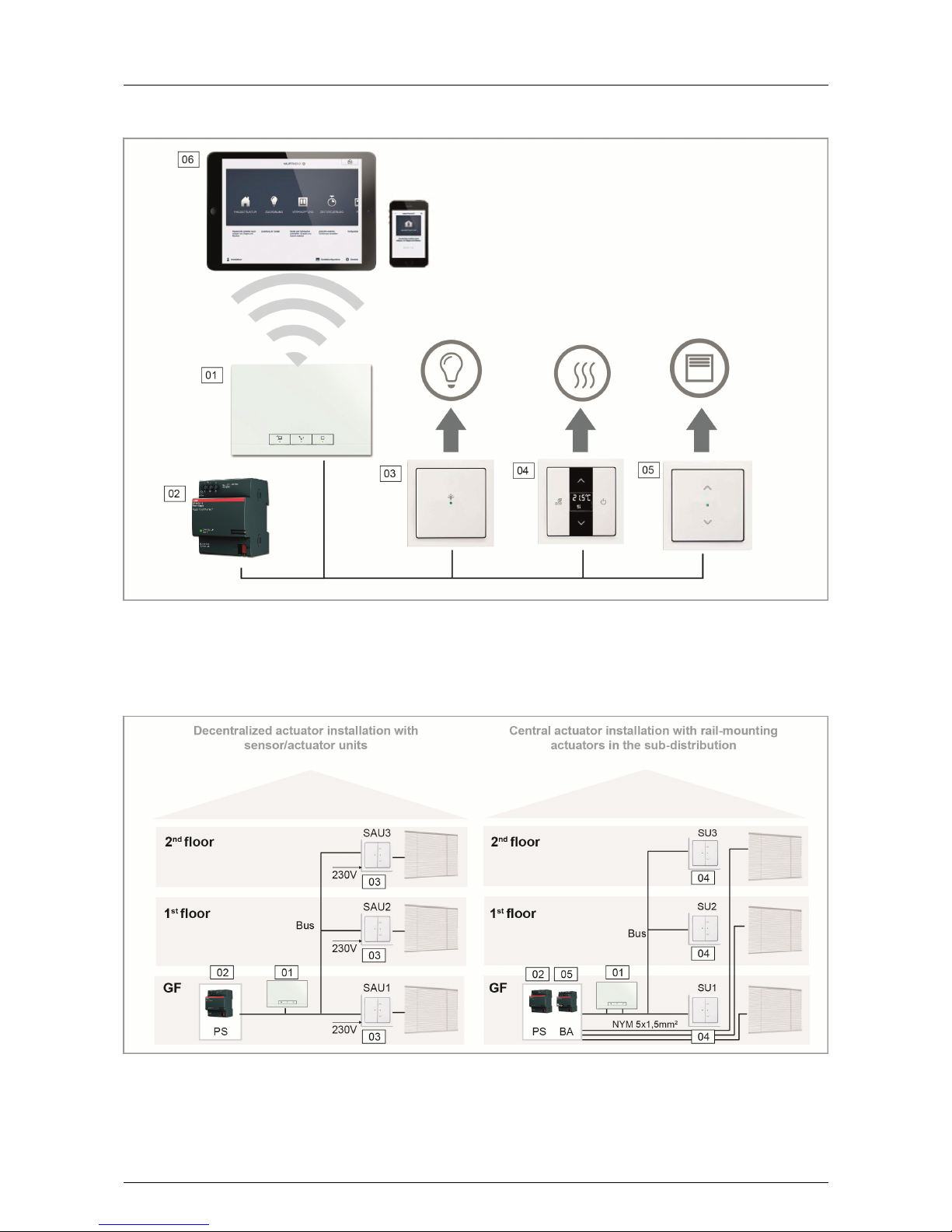
A free@home system is made up of the following devices:
» a System Access Point,
» a power supply,
» sensors for local operation,
» actuators for switching loads.
Performance features
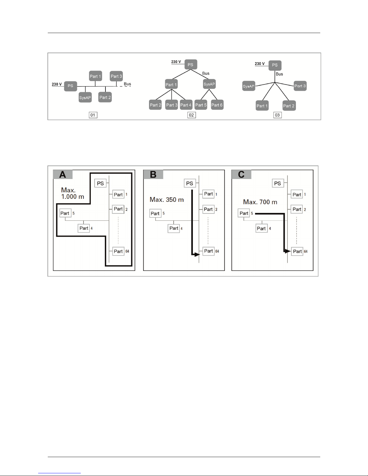
Up to 64 devices can be installed in a system
(power supply is not included).
The following versions of devices are available:
System devices
» System Access Point
» Power supply
Sensors
» Control elements
» Panels
» Binary inputs
» Room temperature controller
» Movement detector
Actuators
» Switch actuators
» Dimming actuators
» Blind actuators
» Heating actuators
Sensors and actuators are each available in construction
types flush-mounted, flush mounted pill and rail-
mounting (MDRC) and can be combined as required
according to application.
The web-based user interface of the System Access Point
can be called up and operated simultaneously by several
participants (computers and/or mobile devices with the
free@home app). This can, depending on the changes
made, lead to losses in performance (the changes take
longer to implement). That is why it is recommended to
operate the user interface with only 4 participants at the
same time.

03 Planning and Installation ABB-free@home®
6 │System Manual
03 Planning and Installation
System Access Point and power supply
(Fig. 1)
The System Access Point offers the opportunity for ac-
cessing the free@home system with the PC or mobile
terminal devices. This allows the functions of the system
to be programmed and remote controlled.
Each system requires a power supply. It uses the voltage
required by the bus subscribers for supplying the bus
communication part of the devices.
Decentralized or central installation of the
actuators (Fig. 2)
The free@home system offers both rail-mounting actua-
tors for central installation in the switch cabinet as well as
sensor/actuator units for decentralized flush-mounted
installation.
Both types of installation can be mixed within the system
as desired.
Advantages of the decentralized installation
» "All-in-one": Sensor and actuator are located in the
one device.
» Function does not need programming since sensor
and actuator have been pre-configured.
» Usual manner of wiring of the 230 V line.
Advantages of the central installation
» Inexpensive channel price due to multiple actuators.
» Easy installation of the sensor technology since only
the bus line is installed in the flush-mounted box.

ABB-free@home®03 Planning and Installation
System Manual │7
Fig. 1 Plan of system
01 - System Access Point
02 - Power supply
03 - Sensor/switching actuator unit
04 - Room temperature controller
05 - Sensor/blind actuator unit
06 - Mobile terminal devices
Fig. 2 Planning of the actuators
01 - System Access Point
02 - Power supply (PS)
03 - Sensor/blind actuator unit (SAU)
04 - Sensor unit (SU)
05 - Blind actuator (BA)

03 Planning and Installation ABB-free@home®
8 │System Manual
Topology of line participants
The free@home system communicates via the data bus.
This means that each participant must be connected to
the bus to be able to communicate with other participants.
Participants
Each free@home device, with the exception of the power
supply, counts as participant. Up to 64 participants can be
connected to the bus.
Note:
The System Access Point also counts as a participant.
Line topology (Fig. 3)
The free@home bus line can be installed in almost any
manner desired.
» Mixing the line topologies of linear, star and tree is
permitted.
» Only rings must not be set up.
» No terminal resistors are required.
Lengths and distances of lines (Fig. 4)
» A - Max. lengths of lines: The lengths of lines within a
line are limited to a total length of max. 1,000 m.
» B - The maximum distance between power supply and
the last participant: max. 350 m.
» C - The maximum distance between two participants:
max. 700 m.
BUS line
The bus line leads to the participants.
» A KNX-certified bus line (J-Y(ST)Y 2x2x0.8) is to be
used.
» Aside from the necessary physical characteristics
(number of wires, cross-section, insulating voltage,
etc.) the bus line can be differentiated immediately
from other low-current lines.

ABB-free@home®03 Planning and Installation
System Manual │9
Fig. 3 Possible topologies
01 - Linear topology
02 - Tree topology
03 - Star topology
PS - Power supply
Part 1 - Participant 1
SysAP - System Access Point
Fig. 4 Lengths and distances of lines

03 Planning and Installation ABB-free@home®
10 │System Manual
Planning of the System Access Point
The System Access Point makes available its own WLAN
during commissioning, so that it can be comfortably pro-
grammed in mobile mode, even when no network infra-
structure is available.
However, in the final state the System Access Point
should be set up as participant within the available net-
work infrastructure.
The System Access Point can be connected to the availa-
ble network infrastructure of the apartment either via the
installed Ethernet port or the installed WLAN antenna.
Connection via WLAN (Fig. 5)
If the System Access Point cannot be connected to the
Internet router via cable, it can be logged into the existing
WLAN network via WLAN as client.
Connection via patch cable (Fig. 6)
If the System Access Point and Internet router are in-
stalled side by side, they can be connected via a patch
cable.
Connection via installation cable in case of structured
cabling (Fig. 7)
If the System Access Point is to be connected via a CAT
installation cable, it can be connected via the RJ45 socket
with an LSA adapter.
Otros manuales para ABB-free home
2
Tabla de contenidos
Otros manuales de Punto de acceso inalámbrico de ABB


