Zareba AC POWERED Manual de usuario

SAVE THESE INSTRUCTIONS
USER’S MANUAL
For AC-Powered Fence Controllers
Part I: Fence Controller Installation
Before You Start . . . . . . . . . . . . . . . . . . . . . . . . . . . p. 2
Fence Controller Installation . . . . . . . . . . . . . . . . . . . . . p. 4
Fence Controller Operation . . . . . . . . . . . . . . . . . . . . p. 10
Model 8200 Installation/Operation . . . . . . . . . . . . . . . . p. 11
Part II: Electric Fencing Basics
Electric Fence Components . . . . . . . . . . . . . . . . p. 12
Electric Fencing Basics . . . . . . . . . . . . . . . . . . . p. 14
Grounding System . . . . . . . . . . . . . . . . . . . . p. 15
Fence Posts . . . . . . . . . . . . . . . . . . . . . . . . p. 17
Insulators . . . . . . . . . . . . . . . . . . . . . . . . . p. 19
Fence Wire . . . . . . . . . . . . . . . . . . . . . . . . p. 20
Gate Openings . . . . . . . . . . . . . . . . . . . . . . p. 22
Lightning/Surge Protection . . . . . . . . . . . . . . . . p. 23
Electric Fence Design . . . . . . . . . . . . . . . . . . . p. 25
Testing/Troubleshooting. . . . . . . . . . . . . . . . . . p. 30
Fence Controller Warranty. . . . . . . . . . . . . . . . . p. 33
USmanual-AC.indd 1 6/24/2010 4:30:04 PM

- 2 -
All Zareba brand pulse-type electric fence controllers meet
Underwriters Laboratories (UL) standards for safety.
WARNING: Read ALL these instructions. Only use
electric fence controller products for the purpose
intended as defined in this manual.
WARNING: Never run more than one fence controller
on the same fence line at one time. The pulse time
between the fence controllers will be too close together
and could be hazardous to animals and people. It
could also damage your fence controllers.
WARNING: Install fence lines powered by separate
fence controllers far enough apart to prevent contact
with both fence lines at the same time. Simultaneously
touching two fences powered by separate energizers
could be hazardous.
WARNING: In brushfire-prone areas, turn the fencer
off on extremely dry days. For backup, be sure others
know how to disconnect the fence controller. Also,
never disconnect wires or approach a fence during
lightning storms.
WARNING: Do not operate fence controllers near any
combustible materials including gasoline, kerosene and
cleaning fluids.
WARNING: Never electrify barbed wire or similar fence
types where an animal or human may become tangled
in the fence or caught against the fence.
WARNING: To reduce risk of electrical shock, do not
remove the fence controller cover. Refer to service
personnel.
Before You Start
USmanual-AC.indd 2 6/24/2010 4:30:05 PM

- 3 -
WARNING: Check local zoning laws for electric
fencing guidelines in your area. Also check with local
utilities before digging to identify any buried cables or
natural gas lines.
In a double-insulated controller, two systems of
insulation are provided instead of grounding. No
means of equipment ground is provided in the supply
cord of a double-insulated controller, nor should a
means for equipment grounding be added to the
controller. Servicing of a double-insulated controller
requires extreme care and knowledge of the system,
and should be done only by qualified service personnel.
Replacement parts for a double-insulated controller
must be identical to the parts they replace.
Tools Required
• Wire cutter/stripper (part no. FWC-1)
• Flathead and phillips screwdrivers
• Adjustable wrench
• Voltage tester (part no. DEFT-1 or RSVT8)
Other Required Components
• Two lengths of 20 KV insulated hook-up wire (one long
enough to connect fence controller to ground system
and one long enough to connect fence controller to
fence line)
• Fence line connector (part no. 07110-96 for steel or
poly wire; PRS2 for poly rope; or PTCC1 for poly tape)
• 6- to 8-foot ground rod(s) (part no. GR8 or 07104-96)
• Ground rod clamps–one per ground rod (part no.
CGR1 or 07105-96)
USmanual-AC.indd 3 6/24/2010 4:30:06 PM

- 4 -
Fence Controller Installation
Ground
connection
AC power plug
Overview of Installed Fence Controller
Fence
connection
USmanual-AC.indd 4 6/24/2010 4:30:06 PM
- 5 -
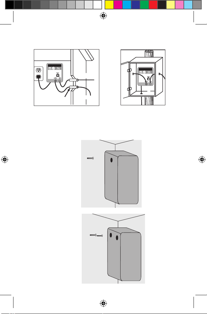
STEP 1: Mount Fence Controller
IMPORTANT: Mount inside or in a waterproof enclosure
Single screw mounting
Double screw mounting
To fence
To ground
Plastic/PVC pipe
Inside installation Outdoor sheltered
installation
USmanual-AC.indd 5 6/24/2010 4:30:08 PM

- 6 -
STEP 2: Connect Ground and Fence Terminals
Connect hook-up wire to
FENCE terminal
Connect hook-up wire to
GROUND terminal
1½“
20KV hook-up wire
– or –
– or –
Your fence controller will
have one of three types of
terminals – strip wire and
connect as shown below
USmanual-AC.indd 6 6/24/2010 4:30:11 PM

- 7 -
Hook-up wire
from fence controller
Hook-up wire to
other ground rods
STEP 3: Connect to Ground System
Check ground system reliability
• IMPROPER GROUNDING WILL AFFECT THE PERFORMANCE OF
YOUR FENCE CONTROLLER! See page 15 for more information
about proper grounding.
NOTE: Connect additional ground rods with hook-up wire and ground rod clamps
Ground rod clamp
(part no.07105-96 or CGR1)
Ground rod
(part no.07104-96 or GR8)
Tip: The fence controller must be grounded sufficiently for the
system to work effectively. Improper grounding can also cause inter-
ference on telephone lines, radios and television and could invalidate
your warranty.
USmanual-AC.indd 7 6/24/2010 4:30:11 PM

- 8 -
STEP 4: Connect to Fence Line
Check fence system reliability
• IMPROPER CONNECTION POINTS WILL AFFECT THE
PERFORMANCE OF YOUR FENCE CONTROLLER!
• Make sure splices and insulators are sound and secure.
Poly tape connection
Poly tape connector clamp
(part no. PTCC1)
Poly rope connection
Poly rope splicer
(part no. PRS2)
Aluminum/Steel/Poly wire connection
Galvanized line clamp
(part no. 07110-96)
USmanual-AC.indd 8 6/24/2010 4:30:12 PM
- 9 -
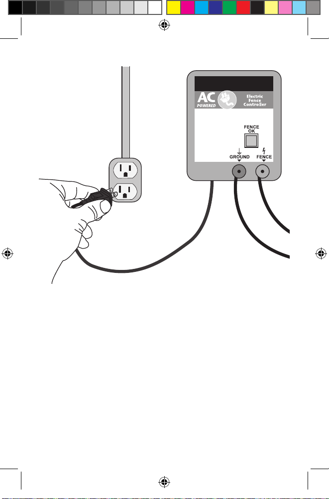
STEP 5: Power Fence Controller
NOTE: Fence controller will
be outputting voltage at this
point – to avoid shock do
not touch fence terminal or
fence wire.
WARNING: For AC-powered fence controllers; do not
modify the plug provided with the controller if it
doesn’t fit into the outlet. Contact a qualified electri-
cian for proper outlet installation.
To reduce the risk of electric shock, these fence control-
lers have a polarized plug (one blade is wider than the
other). This plug will fit in a polarized outlet only one
way. If the plug does not fit fully in the outlet, reverse
the plug. If it still does not fit, contact a qualified electri-
cian to install the proper outlet. Do not change the plug
in any way.
USmanual-AC.indd 9 6/24/2010 4:30:13 PM

- 10 -
Ground terminal
• connect to ground rod
Fence terminal
• connect to fence line
Fence OK
• flashes 40-60 times/minute
when voltage output is OK
• flashes at slower rate when
fence line voltage is low
Fence OK
• flashes when voltage is
on fence line
Fence Controller Operation
USmanual-AC.indd 10 6/24/2010 4:30:14 PM
Tabla de contenidos
Otros manuales de Controladores de Zareba


