Xetron STC-1000Pro Manual de usuario

Smart Temperature Controller Series
STC-1000Pro User Manual
Smart Digital Thermostat
No wiring , No hassle

Smart Temperature Controller Series
STC-1000Pro User Manual
Intelligente Temperaturregler-Serie
STC-1000Pro Benutzerhandbuch
Série de thermostat intelligent
Mode d’emploi STC-1000Pro
Serie del controlador de temperatura inteligente
Manual de uso de STC-1000Pro
Serie di Termostati Intelligenti
Manuale di istruzione di modello STC-1000Pro
CONTENTS
1-9
10-18
19-27
28-36
37-45

1.0 Overview
The STC-1000Pro is a plug-and-play smart digital temperature controller. It has two pre-wired
heating and cooling outlets that automatically keep your appliances at ideal temperatures and
keep them safe and reliable due to V-O classified flame-retardant ABS materials. Meanwhile,
its three-button design and 2.5" LCD provide intuitive temperature viewing and parameter
settings, such as high/low temperature alarm, temperature calibration, "C/"F unit switch, and
cooling protection time. The STC-1000Pro with UK/EU/US versions can be widely used in areas
that require automatic temperature controls, such as homebrewing, aquariums, incubation, pet
breeding, seedling heat mats, culture fermentation.
In the box
* Available in UK/EU/US version
Power Plug*
Temperature Probe
Main Controller
Cooling and Heating
Outlets*
1
English

2
1.1 Display
Note:
1Csp(Cooling start point) = TS(Temperature Set-point) + CD(Cooling Dierential)
2Hsp(Heating start point) = TS(Temperature Set-point) - HD(Heating Dierential)
2 3 4 5
6
7
9
10
8
1
1
2
3
4
PV
5
SV
6
7
Csp1
8
9
10
Parameters
Hsp2
Cooling Mode
Wi-Fi Connection Status
Alarm
Heating Mode
Settings
Current Value
Set Value
Cooling start point
Heating start point
See 3.0 Parameter Instruction
No. Icon Function

3
2.2 Power On
2.0 Operation
2.1 Probe Installation
Incorrect operation may cause serious damage to you or your device.
Please make sure you read and understand the following procedures before starting.
Plug the temperature probe fully to the bottom of the main controller's headphone jack.
Otherwise, a buzzer alarm will be triggered, and the "Err" code will show on the LCD after
powering the controller.
Fully Plug In
Plug the controller into a 100V to 250V power outlet, the LCD will light up and display
temperature and other parameters.

Press and hold button for 3 seconds to enter the parameter setting mode, the buzzer will
beep and the LCD will display icon.
Press button to switch to the next parameter, then press or to increase or decrease
the setting value; or long press or to increase or decrease quickly.
Press and hold for 3 seconds to save settings and exit; or the controller will save and exit
setting mode after 15 seconds of inactivity.
See the flow chart below for quick parameter setting procedures:
4
2.3 Parameter Viewing
Press or to enter parameter viewing mode.
Press to view the parameters and relative values in ascending order:
TS→CD→HD→PT→AH→AL→CA. The parameter details are in 2.4 Parameter Settings.
Note: The controller will automatically exit viewing mode after 5 seconds of inactivity.
Press SET button
for 3s
Press SET button for
3s/ 15s of inactivity
Temperature
Set Value
Cooling
Dierential
Temperature
Calibration
Temperature
Unit
Low
Alarm Limit
Heating
Dierential Protection Time
High
Alarm Limit
2.4 Parameter Settings
STC-1000Pro supports parameter settings by buttons.
Button Operation

5
3.0 Parameter Instructions
1 2 3 5 6 7
8
4
Parameter Instructions
No.
Code
Function
Setting Range
Default
1
TS
Temperature
Set-point
-40 - 110 25
-40 - 230 77
2
CD
Cooling
Dierential
0.2 - 15 2.0
1 - 30 3
3
HD
Heating
Dierential
0.2 - 15 2.0
1 - 30 3
4
PT
Protection Time
0 - 10 3
5
AH
High Alarm Limit
-40 - 110 35
-40 - 230 95
6
AL
Low Alarm Limit
-40 - 110 0
-40 - 230 32
7
CA
Temperature Calibration
-10 - 10 0
-1 5 - 1 5 0
8
CF3
Temperature Unit
°C/°F
°C
°F
°C
°F
°C
°F
°C
°F
°C
°F
°C
°F
C
Unit
min
---
Note: 3 The°C/°F icon will flash on the LCD during temperature unit settings.

3.1.1 Temperature Setting - TS, HD, CD, PV, SV
When the controller is in normal operation, the PV displays the current value; the SV displays
the set value by adjusting the TS (Temperature Set-point), HD (Heating Dierential), and CD
(Cooling Dierential) parameters (Cooling Dierential). It will switch between cooling and
heating modes.
Cooling Mode:
● When PV (Current Value) ≥ TS (Temperature Set-point) + CD (Cooling Dierential), the
controller enters the cooling mode, the cooling icon is on and the cooling outlet starts
to output.
If the cooling icon flashes, the compressor is under protection status, please see 3.1.2
Protection Time - PT for further information.
● When PV (Current value) ≤ TS (Temperature Set-point), the controller exits the cooling
mode, the cooling icon is o.
Heating Mode:
● When PV (Current Value) ≤ TS (Temperature Set-point) - HD (Heating Dierential), the
controller enters heating mode, the heating icon is on and the
heating outlet starts to output.
● When PV (Current Value) ≥ TS (Temperature Set-point), the controller exits heating
mode, the heating icon is o.
Example:
If set TS = 25°C, CD = 3°C, HD = 3°C:
Csp (Cooling start point) = TS + CD = 28°C,
Hsp (Heating start point) = TS - HD = 22°C.
When PV (current value) ≥ 28°C(Csp), the controller automatically enters cooling mode. When
PV ≤ 25°C(TS), the controller automatically exits cooling mode.
When PV ≤ 22°C(Hsp), the controller automatically enters heating mode. When PV ≥ 25°C(TS),
the controller automatically exits heating mode.
6
3.1 Parameter Functions
°C
/
°F
28/82.4 Csp (Cooling start point)
Hsp (Heating start point)
TS (Temperature Set-point)
CD (Cooling Dierential)
HD (Heating Dierential)
25/77
22/71.6

7
3.1.2 Protection Time - PT (Cooling Mode Only)
Frequent start/stop may influence or even shorten the service life of your appliance; we
suggest you to set the parameter PT (Protection Time, i.e. cooling start delay time), to protect
your appliance. Please set it according to your requirements.
Example: When PT is set to 3 minutes, PV (Current Value) > Csp (Cooling start point), the
controller will enter cooling mode if either condition below is satisfied:
● The controller is powered on for more than 3 minutes;
● The interval between two adjacent cooling modes is more than 3 minutes.
3.1.3 High Alarm Limit - AH
When PV (Current Value) ≥ AH (High Alarm Limit), high temperature alarm will be triggered,
the LCD displays error code "EAH", the icon and buzzer beeps promptly. Press any button
to mute the buzzer, but the error code will remain until PV < AH.
3.1.4 Low Alarm Limit - AL
When PV (Current Value) ≤ AL (Low Alarm Limit), low temperature alarm will be triggered, the
LCD displays error code "EAL", the icon and buzzer beeps promptly. Press any button to
mute the buzzer, but the error code will remain until PV > AL.
Note: The controller will work normally during AH or AL alarms.
3.1.5 Temperature Calibration - CA
When PV (Current Value) deviates from the standard or actual temperature, please use the
parameter CA to correct it. The calibration value could be positive, 0 or negative and PV
(calibrated) = PV (before calibration) + CA (temperature calibration).
3.1.6 Celsius/Fahrenheit - CF
The controller supports Celsius or Fahrenheit display. The US version default unit is in Fahren-
heit, the UK/EU version default is in Celsius. If the default is dierent from your preferred
unit, please modify the parameter CF as shown in 2.4 Parameter Settings.
Note: If you only need to connect one appliance, or do not use the outlet for a long time, please
put it away to prevent potential damage to the controller.
8
For your personal and appliance's safety, we suggest you power on the controller after
the installation finishes.
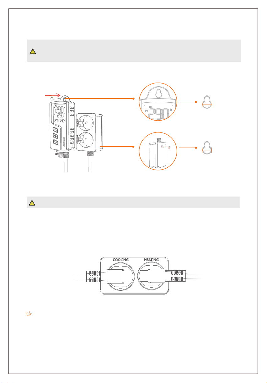
This controller supports hanging-mount only, please check and confirm the installation distanc-
es and nails size before installation. The details are shown below for reference:
Take care when using electricity!
Please plug your refrigeration and heating appliances into the corresponding cooling and
heating outlets to the controller.
If all status is normal, the controller will start cooling or heating automatically according to the
parameters, the corresponding icon will show prompt to indicate the current working status.
4.0 Installation
5.0 Cooling/Heating Outlet
Φ7mm
Refrigeration
Appliance
Heating
Appliance
Φ9mm
Tabla de contenidos
Idiomas:


