WTE MReX-PCB Manual de usuario

Christchurch, NZ
MReX-PCB User Guide V1.02
MReX-PCB
Mini Transmitter
User Guide
© WTE Limited, 2021 – Christchurch New Zealand Page 1 of 13

Christchurch, NZ
MReX-PCB User Guide V1.02
Table of Contents
Introduction..........................................................................................................................................3
Electrical...............................................................................................................................................4
PCB Pinout...........................................................................................................................................5
Programming the M eX Module.........................................................................................................6
Inputs....................................................................................................................................................6
LEDs Outputs.......................................................................................................................................7
LED/Piezo esistor Configuration..................................................................................................8
Piezo connection............................................................................................................................10
Physical Dimensions..........................................................................................................................12
Disclaimer...........................................................................................................................................13
© WTE Limited, 2021 – Christchurch New Zealand Page 2 of 13

Christchurch, NZ
MReX-PCB User Guide V1.02
Introduction
This user guide describes configuration and use of the WTE M eX-PCB. This PCB allows simple
integration into a system and incorporates the M eX-460 Module. For command use and detailed
operation, consult the M eX-460 User Manual. Not shown is the antenna connection. This may be
an SMA connector fitted to the red M eX-460 module (with antenna) or a 16cm wire (one quarter
the wavelength of the frequency of operation).
© WTE Limited, 2021 – Christchurch New Zealand Page 3 of 13

Christchurch, NZ
MReX-PCB User Guide V1.02
Electrical
The following schematic shows how the M eX-460 module is routed to connection pads.
© WTE Limited, 2021 – Christchurch New Zealand Page 4 of 13

Christchurch, NZ
MReX-PCB User Guide V1.02
PCB Pinout
Pin # Description
1GND
2GND
3Contact Input 3 (Connection to input must
be volt free). Pull to GND to operate.
4Contact Input 2 (Connection to input must
be volt free). Pull to GND to operate.
5Contact Input 1 (Connection to input must
be volt free). Pull to GND to operate.
6Piezo. T is pin is electrically tied to pin 7
7Green LED – Cat ode (open drain output)
8Green LED + Anode (not connected if LED
is powered externally)
9Piezo. T is pin is electrically tied to pin 8
10 Contact Input 4 (Connection to input must
be volt free). Pull to GND to operate.
11 Contact Input 5 (Connection to input must
be volt free). Pull to GND to operate.
12 Programming VCC
13 GND
14 Serial TTL IN
15 Serial TTL OUT
16 Red LED – Cat ode (open drain output)
17 Red LED + Anode (not connected if LED is
powered externally)
© WTE Limited, 2021 – Christchurch New Zealand Page 5 of 13
Christchurch, NZ
MReX-PCB User Guide V1.02
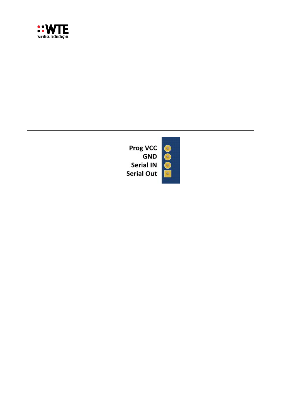
Programming the MReX Module
The Programming Header contains a 5V (VCC) pin which can be used to power the M eX Module
for loading configuration or uploading new firmware.
Do NOT apply vol age o his pin if ba eries are fi ed.
Note: Serial connection is 3.3V TTL. The M eX-P OG USB to serial adaptor can be provided
for serial interfacing.
Inputs
efer to the M eX Module manual (Input Hardware Connection) for example of connections
© WTE Limited, 2021 – Christchurch New Zealand Page 6 of 13

Christchurch, NZ
MReX-PCB User Guide V1.02
LEDs utputs
Connecting the LEDs using Open Drain (bypassing PCB resistors)
The LED outputs are open drain/collectors suitable for sinking a maximum of 50mA. The example
is being used to drive an LED from an external supply. Should the output be presented to potential
ESD conditions (such as any terminal screw or external connection), ESD devices should be fitted.
If the output is to be used to control a small relay, it is essential that a flyback diode is fitted across
the coil of the relay.
Only the Cathode connections of the LEDS are shown here. They are connected to an open drain
output. As shown in the simplified schematic above, it is the users responsibility to select a resistor
that suits the application, and then connect to a suitable power source that has a common GND.
© WTE Limited, 2021 – Christchurch New Zealand Page 7 of 13

Christchurch, NZ
MReX-PCB User Guide V1.02
LED/Piezo Resistor Configuration
The following resistor configuration information describes how to modify the M eX-PCB if LEDs
are to be used powered directly from the fitted AAA battery pack, or how to fit a piezo sounder (and
required components).
1 is used to limit current through the green LED/Piezo. Typical LED value resistor value from
220 to 470 . When a piezo sounder is fitted 1 = 47 .
2 is used by the piezo to improve audio response (1K typically). The resistor fitted should ideally
be selected to produced the greatest audio output.
3 is used to limit current through the ed LED. Typical LED value resistor value from 220 to
470 .
When the command * X_ENABLE=0 is sent to the M eX (disabling the receiver), the green LED
operation changes so that instead of flashing once a second, this output is modulated, so that when
connected to a piezo sounder, a beep will be heard prior to input activated transmissions.
© WTE Limited, 2021 – Christchurch New Zealand Page 8 of 13

Christchurch, NZ
MReX-PCB User Guide V1.02
© WTE Limited, 2021 – Christchurch New Zealand Page 9 of 13

Christchurch, NZ
MReX-PCB User Guide V1.02
Piezo connection
The following images guide the connection of the piezo and required resistors.
© WTE Limited, 2021 – Christchurch New Zealand Page 10 of 13
Tabla de contenidos
Otros manuales de Transmisor de WTE


Manuales populares de Transmisor de otras marcas


Dejero
Dejero EnGo 3x Manual de usuario

Rosemount
Rosemount 4600 Manual de usuario

Speaka Professional
Speaka Professional 2342740 Manual de usuario

trubomat
trubomat GAB 1000 Manual de usuario

Teledyne Analytical Instruments
Teledyne Analytical Instruments LXT-380 Manual de usuario

Rondish
Rondish UT-11 Manual de usuario


